From Concept to Production Overcoming the Challenges of Fan Blade Tooling
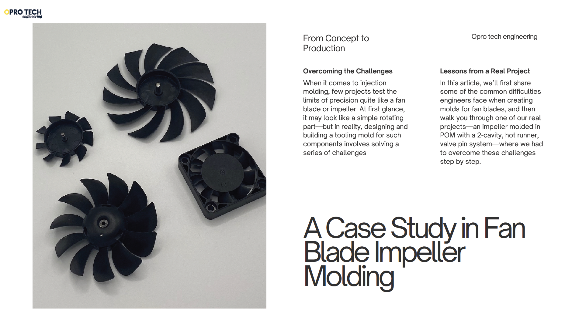
When it comes to injection molding, few projects test the limits of precision quite like a fan blade or impeller. At first glance, it may look like a simple rotating part—but in reality, designing and building a tooling mold for such components involves solving a series of challenges: complex blade geometry, thin airfoil sections, balance control, cooling design, and strict dimensional tolerances.
In this article, I’ll first share some of the common difficulties engineers face when creating molds for fan blades, and then walk you through one of our real projects—an impeller molded in POM with a 2-cavity, hot runner, valve pin system—where we had to overcome these challenges step by step.
Designing and building a tooling mold for fan blades is indeed a high-precision and challenging task.
1. Fan Blade Design Complexity
Fan blades are not simple shapes—they usually have:
- Twist along the length for aerodynamic efficiency.
- Airfoil shape with precise curvature for optimal airflow.
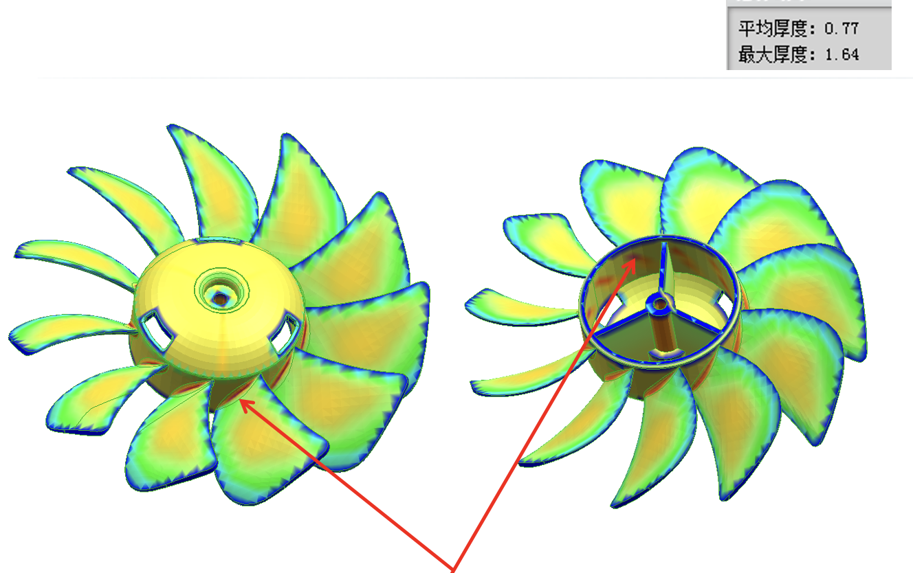
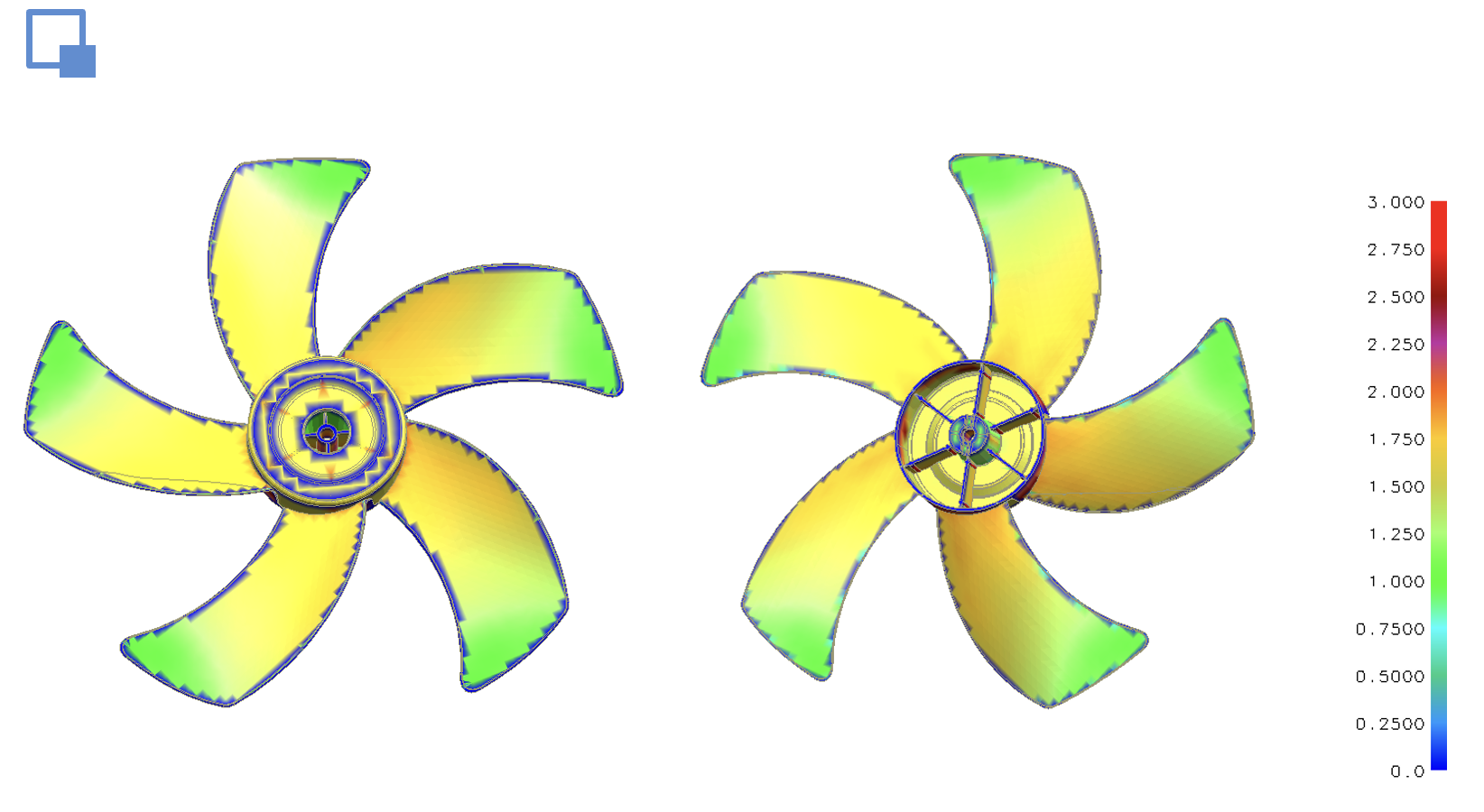
- Variable thickness for strength and weight optimization.
- Fine edge details (leading/trailing edges) that are fragile and prone to flash or deformation during molding.
These features make tooling design very critical.
2. Material Considerations
The choice of plastic or composite affects mold design:
- ABS, PC/ABS, PBT, PPS—common engineering plastics used for blades.
- Glass-fiber or carbon-fiber reinforced materials require careful draft angle design because they shrink differently and are abrasive on the mold.
3. Mold Design Challenges
Fan blade molds often need:
- Precision cavities: The airflow performance depends on maintaining tight tolerances, sometimes ±0.05 mm or better.
- Complex parting lines: Twisted, curved blades often require slider cores or lifters to release the undercuts.
- Multi-cavity vs single cavity: High-volume production may need multiple cavities, but aligning complex geometry is harder.
- Surface finish: Airfoil smoothness is crucial, requiring polished surfaces in the mold.
4. Injection Molding Challenges
- Flow balance: Uneven flow can cause warping, short shots, or knit lines.
- Cooling design: Fan blades are thin and twisty, so conformal cooling channels are often used.
- Cycle time vs quality: Faster cycles risk deformation; longer cycles increase cost.
- Warping and residual stress: Must be minimized with precise material selection, mold temperature control, and packing pressure.
5. Precision & Inspection
- Blades must be measured with CMM (coordinate measuring machine) for angles, twist, and thickness.
- Small deviations can drastically affect airflow efficiency and noise levels.
6. Tooling Solutions
To meet these challenges, engineers often use:
- Slider cores or lifters for undercuts.
- Hot runner systems to reduce waste and improve flow consistency.
- Conformal cooling via 3D printed channels for even temperature distribution.
- High-grade steel (like H13 or S136) to handle precision and repeated cycles without wear.
These challenges are not just theoretical—they come up in nearly every fan blade tooling project, regardless of material or application.
That’s why mold design requires not only technical know-how, but also flexibility to adapt solutions to each client’s unique requirements.
To illustrate this, let me share a recent project we completed: the design and manufacture of a 2-cavity hot runner mold for a POM fan blade impeller. This case highlights how we addressed the common difficulties in practice, and how specific design decisions—such as gate location and cooling system layout—played a key role in achieving success.
Designing and Manufacturing a Precision Tooling Mold for a Fan Blade Impeller
1. Introduction
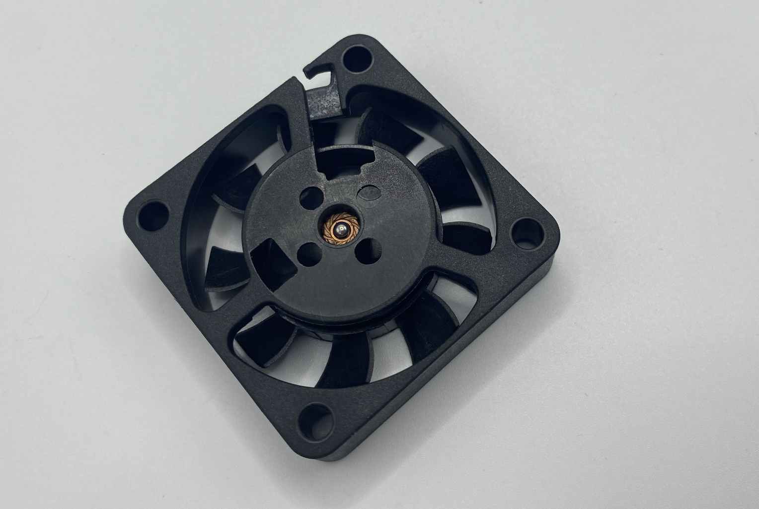
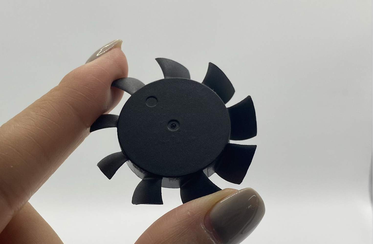
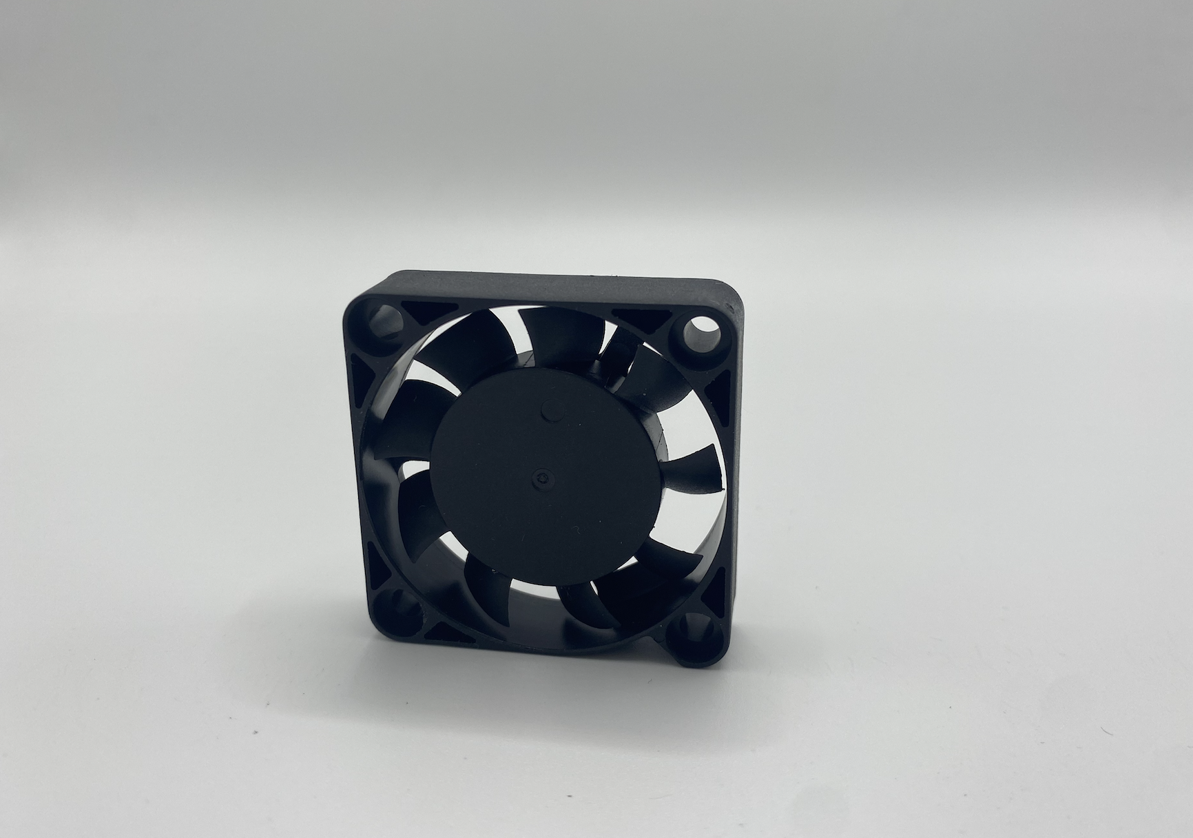
Fan blade impellers are critical components in applications such as automotive cooling, HVAC systems, and household appliances. Their performance depends not only on aerodynamic design but also on manufacturing precision. Small dimensional deviations can lead to imbalance, vibration, noise, and reduced efficiency.
Tooling design for such a component is a complex engineering challenge. In this case study, we present the design and manufacturing of a 2-cavity injection mold for a fan blade impeller, using POM material, with hot runner valve pin gating (2 nozzles), and H13 hardened steel (HRC48–52) for the core and cavity.
2. Material Selection: POM (Polyoxymethylene)
The impeller is molded in POM (acetal) due to its mechanical and processing advantages:
· High stiffness and dimensional stability: critical for maintaining blade geometry under load.
· Low friction coefficient: reduces wear when operating in rotating systems.
· Excellent fatigue strength: supports repeated high-speed rotation.
· Low moisture absorption: ensures dimensional accuracy in varying humidity.
Molding considerations for POM:
· Shrinkage rate: ~1.8%–2.1% depending on wall thickness.
· Tendency for warpage if cooling is not uniform.
· High mold surface temperature (80–100 °C) required for best flow and surface finish.
3. Mold Configuration
Cavity Layout
· 2-cavity design: balances productivity and mold size, while maintaining high precision.
· Mirror-image layout applied to ensure balanced cooling and minimize mold footprint.
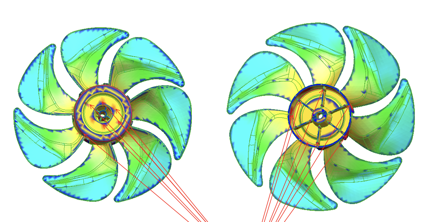
Gating System – Design Decision
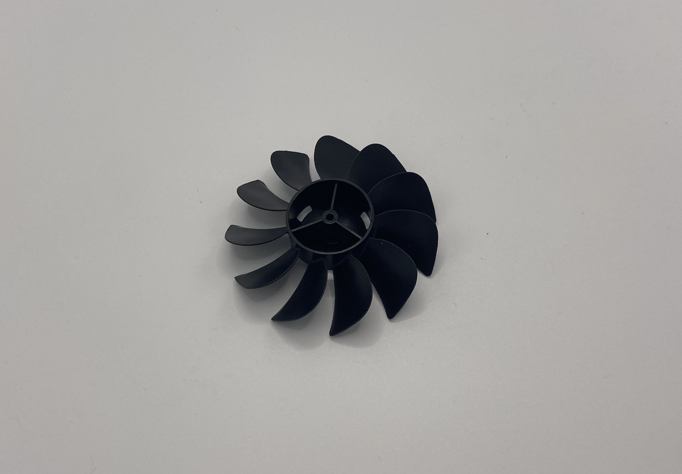
During the design phase, the team initially proposed placing the injection gate at the center of the impeller hub to achieve the most balanced filling pattern.
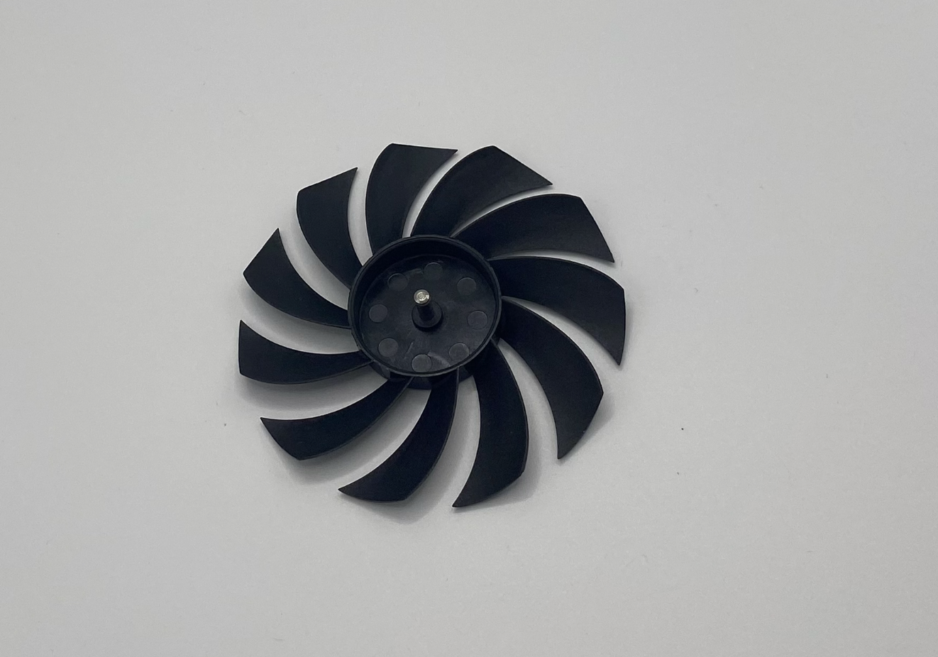
· Client requirement: rejected the central gate, since the middle hub had to remain hollow, smooth, and visually clean.
· Final solution: valve pin gates placed on the side surface of the impeller.
· Mold flow analysis was performed to verify filling balance and eliminate potential weld lines or air traps. The optimized side gating achieved uniform filling without compromising the client’s hollow-center requirement.
Steel Selection
· Cavity/Core: H13 tool steel
o Heat-treated to HRC48–52 for wear resistance and dimensional stability.
o Excellent thermal fatigue resistance for high-temperature POM molding.
o Polishing capability suited for airfoil surfaces.
· Mold Base: P20 steel for structural support and machinability.
4. Design Challenges and Solutions
4.1 Aerodynamic Geometry
· Twist and curvature of blades required 5-axis CNC machining for cavity and core.
· Airfoil surfaces polished to Ra ≤ 0.2 µm for smooth airflow.
4.2 Parting Line Control
· Leading and trailing edges of blades are fragile.
· Optimized parting line placement to minimize flash.
· Venting slots (0.02–0.03 mm deep) added near blade tips to prevent air traps.
4.3 Cooling System Options
Uniform cooling was critical to avoid warpage in the twisted blades. Two cooling design concepts were studied:
1. Square-circle cooling system – provided better structural strength and straightforward machining.
2. Round-circle cooling system – closer contour following around the impeller hub for more uniform temperature distribution.
Both options were validated with thermal simulations. The final solution combined the advantages of both layouts to achieve effective cooling and dimensional stability.
4.4 Ejection System
· Uniform ejection required to avoid blade deformation.
· Combination of ejector pins at blade hub and stripper plate support for balance.
· Ejector pin placement verified by mold flow analysis to minimize stress concentration.
4.5 Balance & Dimensional Accuracy
· Impeller must rotate smoothly without vibration.
· Mold designed to maintain ±0.05 mm tolerance on critical dimensions.
· CMM (Coordinate Measuring Machine) used for inspection after each mold trial.
5. Manufacturing Process
1. Rough CNC machining of cavity and core blocks.
2. Heat treatment of H13 to HRC48–52 for hardness and stability.
3. High-speed CNC finishing on 5-axis machines for aerodynamic profiles.
4. EDM (Electrical Discharge Machining) applied for sharp corners and hub details.
5. Polishing process:
o Pre-polish with diamond paste.
o Mirror polishing of airfoil surfaces for aerodynamic performance.
6. Hot runner system installation: valve pin alignment and thermal balancing.
7. Mold assembly with precision fit to ensure alignment of core/cavity and gating system.
6. Mold Trial and Optimization
First Trial (T0)
· Checked for short shots, warpage, flash, and sink marks.
· Mold flow analysis confirmed good filling pattern from side gating.
Adjustments
· Packing pressure adjusted to eliminate minor shrinkage at the hub.
· Cooling cycle refined after comparing square-circle and round-circle designs.
Validation
· Cycle time optimized to 40 seconds per shot.
· Dimensional accuracy confirmed via CMM report.
· Rotor balance tested dynamically to confirm vibration-free operation.
7. Results and Achievements
· Stable production of impellers with consistent dimensional accuracy.
· Client’s requirement of a smooth hollow hub was fully met.
· Long mold life ensured by hardened H13 core/cavity.
· Clean gate appearance from valve pin system.
· High precision achieved: critical tolerance held within ±0.05 mm.
8. Conclusion
This project highlights the complexity of designing and manufacturing a high-precision fan blade impeller mold. Success required:
· Careful material selection (POM).
· Optimized hot runner valve pin system with side gating.
· Hardened H13 steel with precision machining and polishing.
· Detailed cooling and ejection design to control warpage and deformation.
· Rigorous dimensional and balance validation.
The decision-making process around gate placement and cooling design illustrates how client requirements and engineering solutions must align. By combining simulation, multiple design proposals, and precision manufacturing, the final mold achieved both technical performance and customer satisfaction.
Future improvements could include conformal cooling channels via additive manufacturing, multi-cavity expansion, and advanced mold flow simulations to further optimize cycle time and balance.
Factory add: No 39, Zhen an west road, Changan town , Dong guan city, China.