GD&T (Geometric Dimensioning and Tolerancing) Guide
Geometric Dimensioning and Tolerancing (GD&T) is a system used to define the geometry of mechanical parts and assemblies in a way that’s independent of the manufacturing process. This allows for consistent and precise production of components across various methods like injection molding, CNC machining, and tooling. GD&T uses a set of symbols to specify the allowable variations in form, orientation, and location of a part’s features, ensuring that parts will fit and function properly when assembled.
Benefits of GD&T for Injection Molding, Tooling, and CNC Machining
1. Precision and Consistency:
- GD&T provides clear, standardized definitions for part features, reducing ambiguity and ensuring that parts are manufactured to consistent quality standards.
2. Enhanced Communication:
- Designers, manufacturers, and quality control teams all use the same symbols, which streamlines communication and reduces errors during the manufacturing process.
3. Cost Efficiency:
- By defining acceptable tolerances and limiting unnecessary tight tolerances, GD&T helps manufacturers optimize production processes, reducing material waste, tool wear, and time spent on rework.
4. Improved Quality Control:
- With GD&T, quality control teams can inspect parts against defined tolerances, ensuring that only parts meeting the required specifications are shipped to clients.
5. Better Fit and Function:
- By using GD&T to precisely define how parts fit together and operate in assembly, manufacturers can produce high-performance products that work together seamlessly in the final assembly.
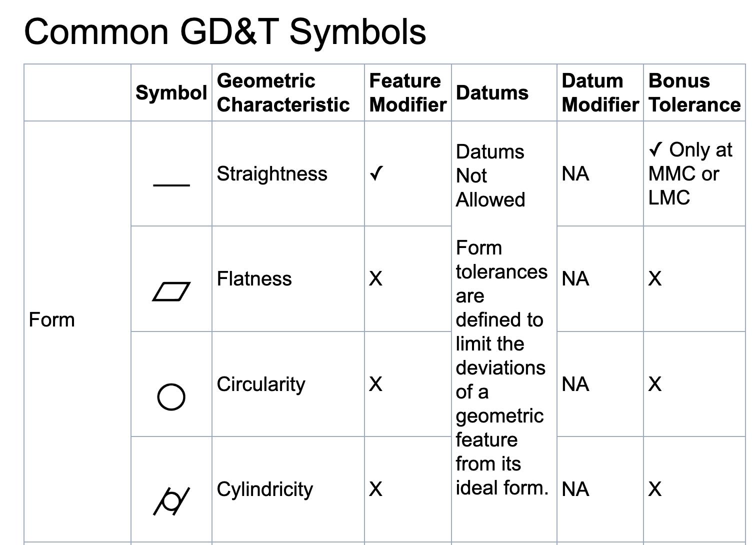
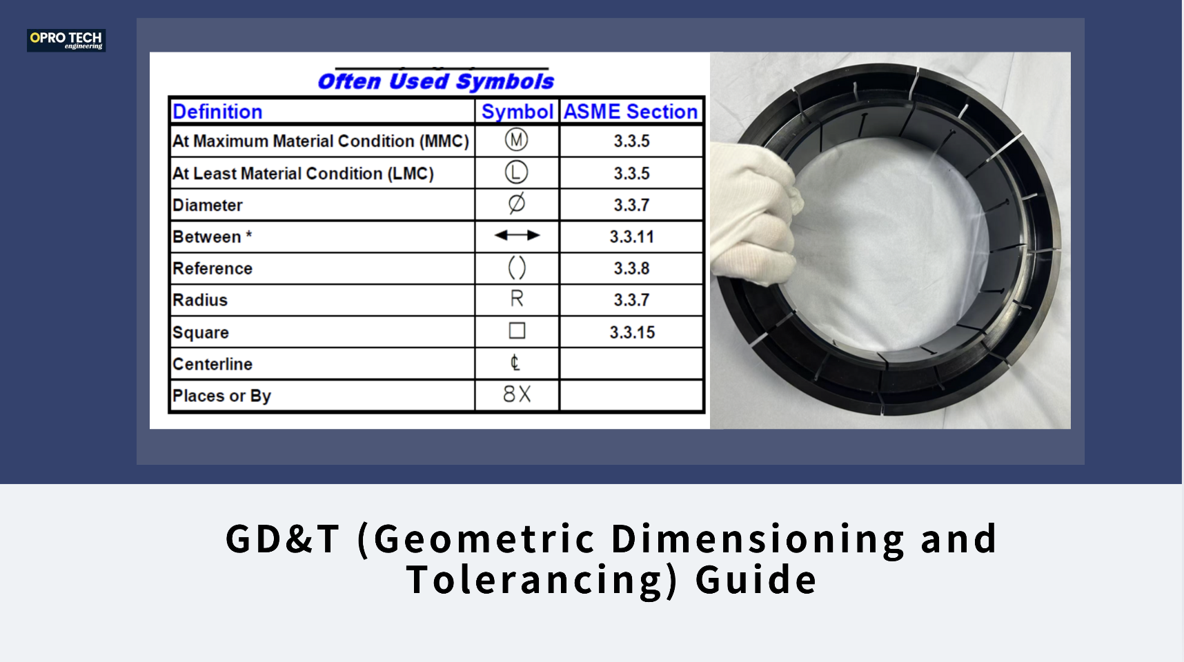
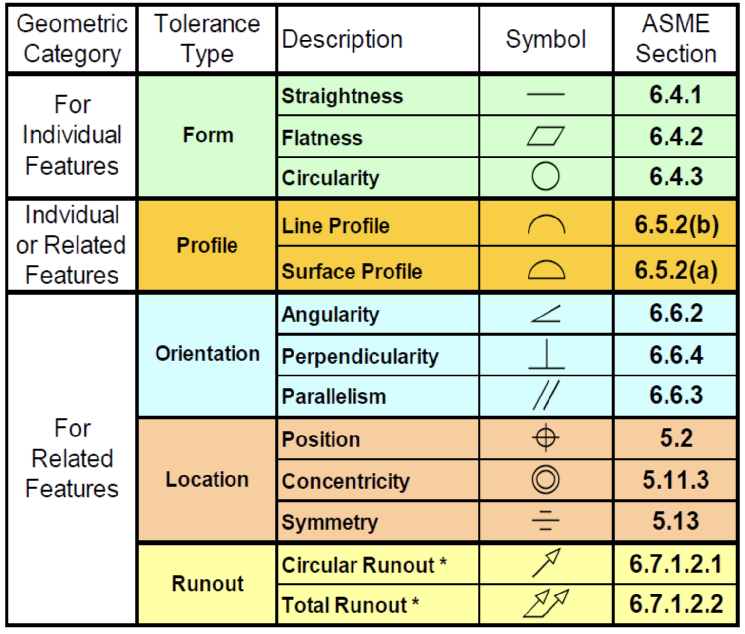
Key GD&T Symbols
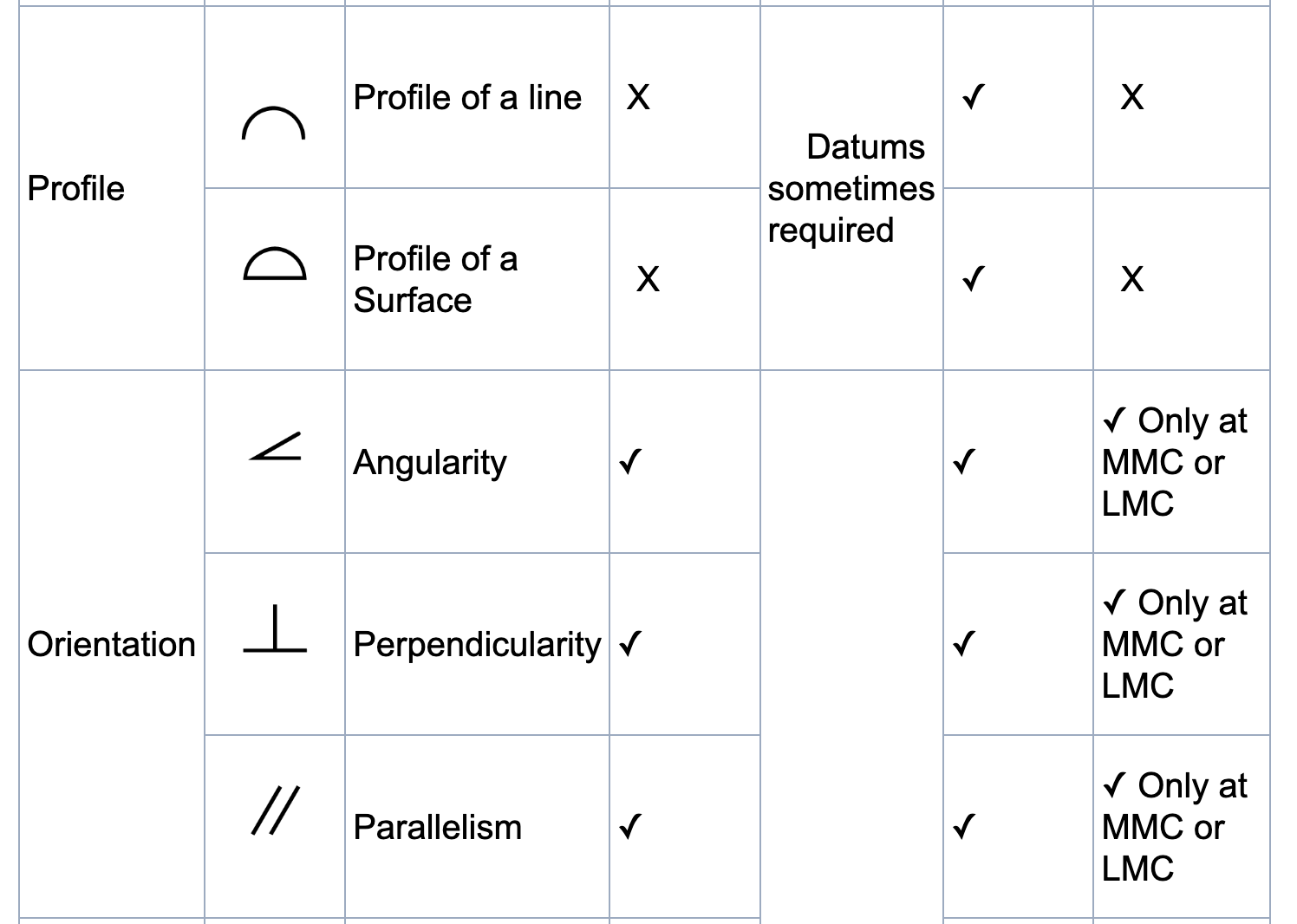
· Profile of a Surface:
- This symbol controls the variation in the shape of a surface. It ensures that the surface remains within a defined tolerance zone. In CNC machining, this could apply to the outer contours of a part, such as a complex bracket or housing.
· Perpendicularity and Parallelism:
- These symbols ensure that features are oriented in the correct direction. For example, if a hole needs to be drilled perpendicular to the surface, perpendicularity tolerance ensures that the hole will be drilled within the specified limits, avoiding misalignment in assemblies.
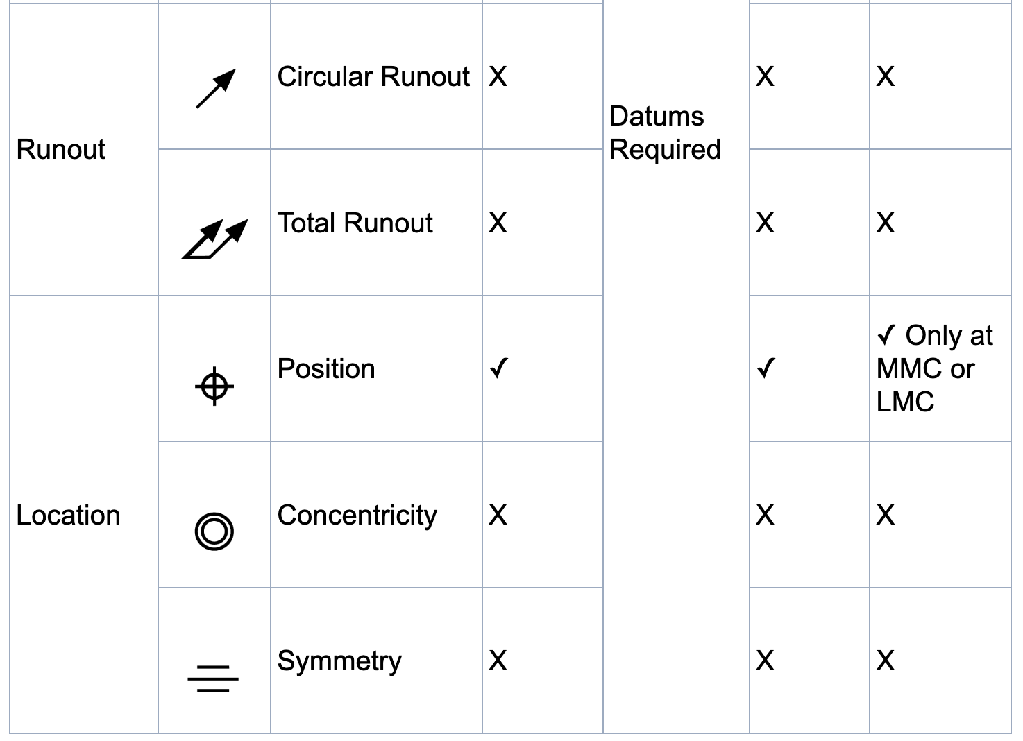
· Concentricity:
- This ensures that two or more features, like holes or shafts, share the same center axis. It’s particularly important when machining components with rotating parts, like gears or shafts, to avoid misalignment that could cause wear or failure.
· Runout:
- Runout controls the total variation of a feature as it rotates around a fixed axis. It’s commonly used for features like shafts and gears to ensure they remain true when rotating, preventing wobbling or failure during operation.
· Location Tolerances (True Position):
- For CNC parts, the true position tolerance ensures that features such as holes, pins, or bosses are positioned within a specified tolerance zone. This ensures precise alignment during assembly, preventing misalignment that could affect product performance.
· Profile of a Line:
- This symbol controls the variation of a feature along a line, which is essential when machining parts with edges or contours that need to be within strict tolerances. It’s useful for components like brackets or plates with complex profiles.
For more detailed information please visit:
https://www.gdandtbasics.com/gdt-symbols/
Factory add: No 39, Zhen an west road, Changan town , Dong guan city, China.