Understanding Dowels, Bolts, and Common Machining Processes: A Guide for Business Professionals in Molds, Mechanical Parts, and Fixture Assembly

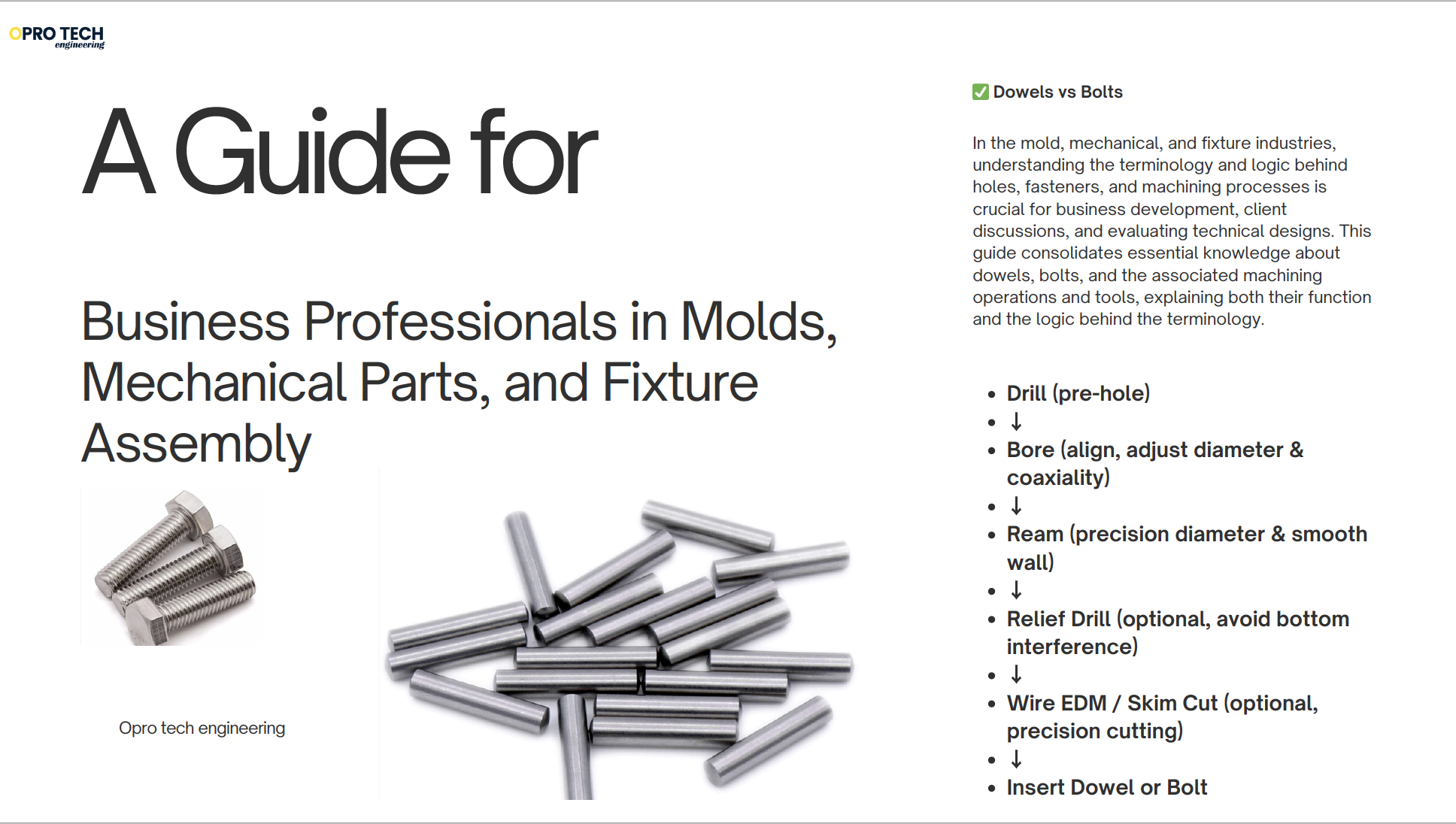
In the mold, mechanical, and fixture industries, understanding the terminology and logic behind holes, fasteners, and machining processes is crucial for business development, client discussions, and evaluating technical designs. This guide consolidates essential knowledge about dowels, bolts, and the associated machining operations and tools, explaining both their function and the logic behind the terminology.
1. Dowels vs Bolts: Purpose and Differences
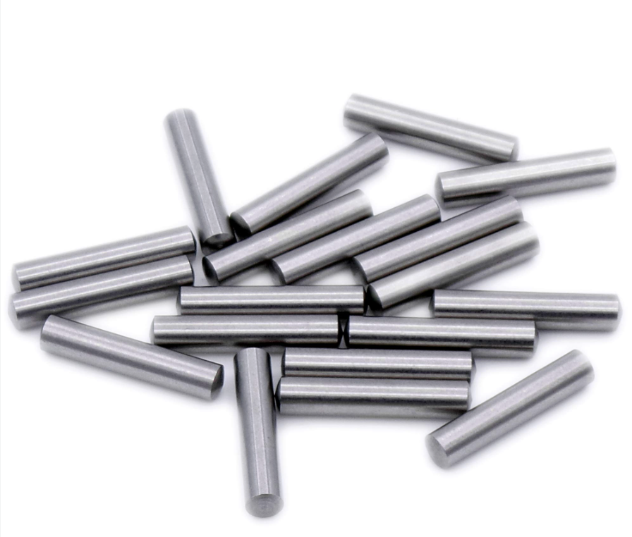
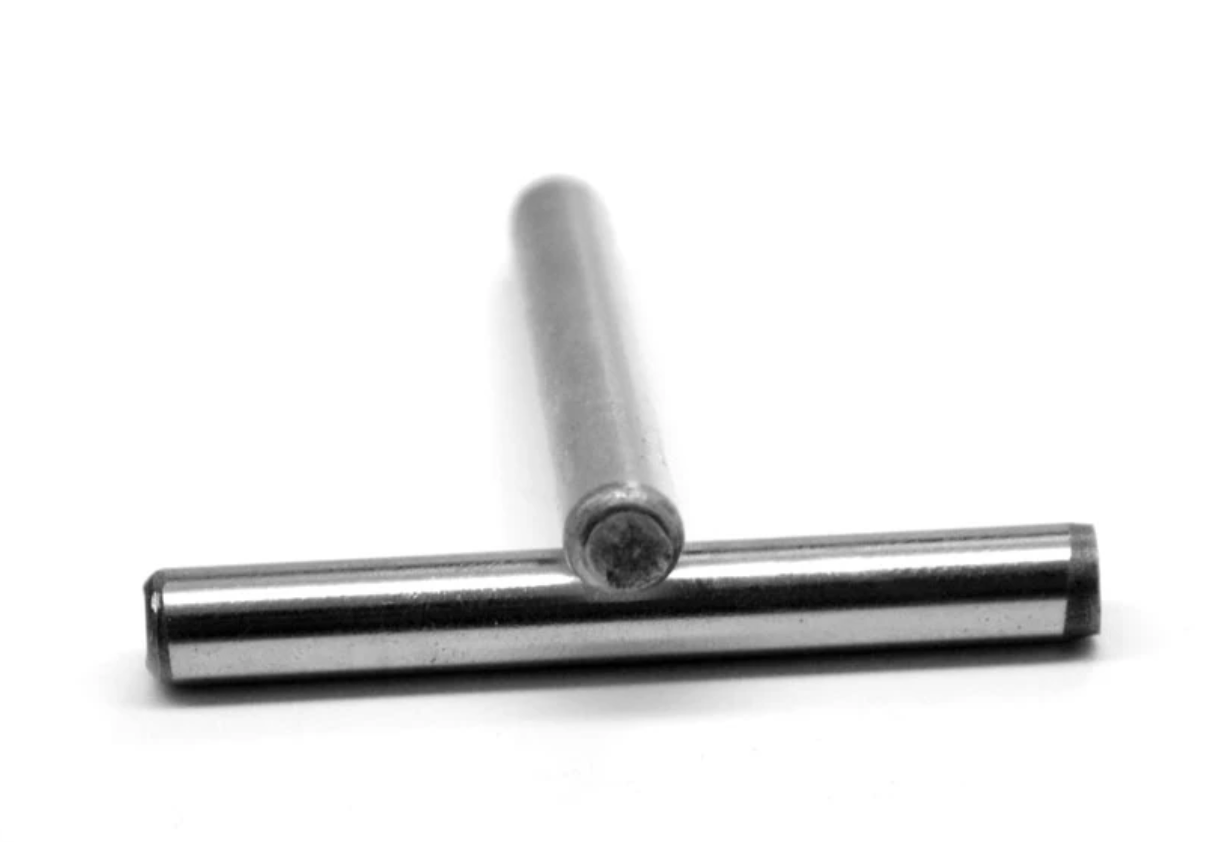
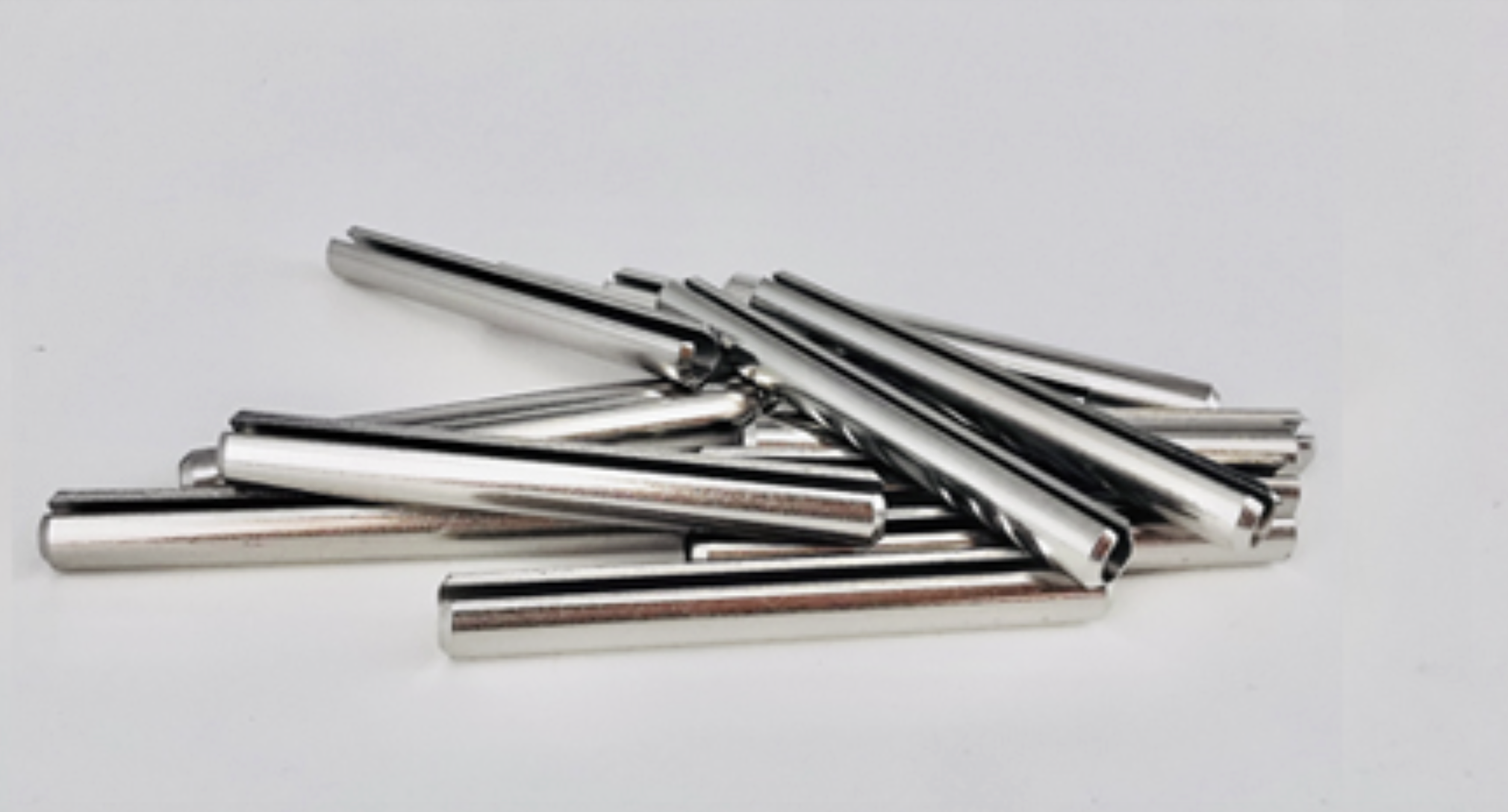
1.1 Dowels (定位销)
- Definition: Cylindrical pins used to precisely locate or align two or more parts.
- Key Features:
- Function: Positioning and alignment only; generally do not carry significant load.
- Shape: Smooth cylindrical pin; precise length and diameter.
- Precision: Very high; holes are often reamed to H7 tolerance for tight fit.
- Installation: Press-fit or light interference; ensures exact alignment.
- Typical Use: Mold plates, die inserts, guide pin holes.
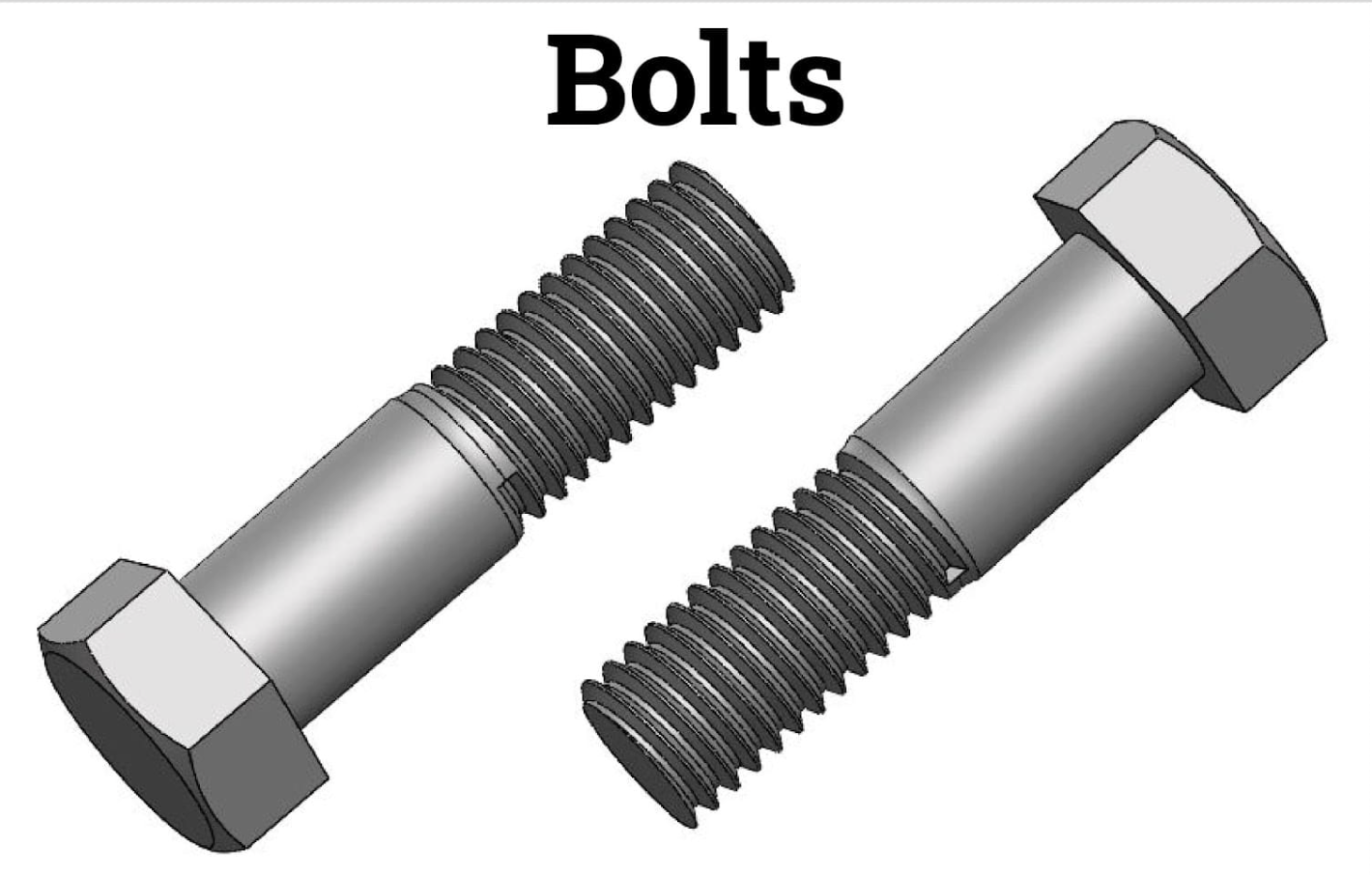
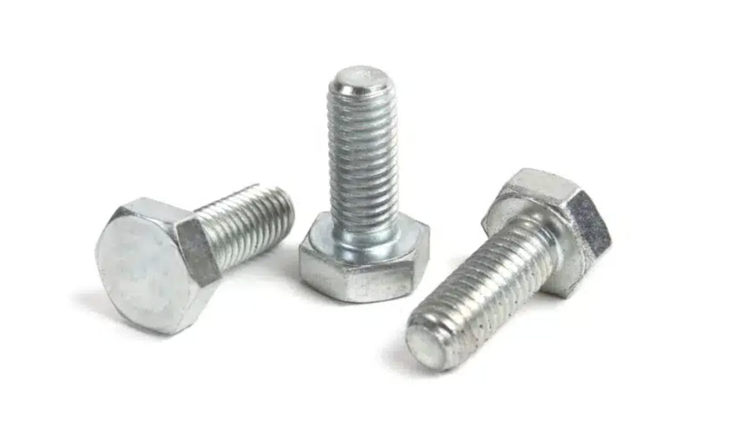
1.2 Bolts (螺栓)
- Definition: Threaded fasteners used to clamp and secure components together, bearing shear or tensile loads.
- Key Features:
- Function: Fixing parts, transmitting forces.
- Shape: Threaded rod + bolt head (hex, socket, flat, countersunk, etc.).
- Precision: Less critical than dowel fit; key is proper thread engagement.
- Installation: Screw into tapped holes or use with nuts.
- Typical Use: Fixing mold plates, mechanical assemblies, machinery components.
1.3 Core Differences
Feature | Dowel | Bolt |
Primary Function | Positioning/Alignment | Fastening/Load bearing |
Shape | Smooth cylinder | Threaded rod + head |
Precision | High (tight fit) | Medium (thread fit) |
Load | Minimal | Tensile/shear loads |
Assembly | Press-fit | Screw in |
Typical Hole | Reamed / relief | Tap drill / counter bore / clearance |
Analogy:
- Dowels: Like the “pins” in a puzzle; parts automatically align.
- Bolts: Like screws holding parts together firmly.
2. Understanding Hole Machining Processes
Machining holes in molds or fixtures is not just “drill a hole.” It involves progressive precision stages, each with specific tools. The main stages are:
2.1 Drilling
- Definition: Creating a hole from scratch using a drill bit.
- Purpose: Make the initial hole.
- Characteristics: Fast, rough; diameter not extremely precise.
- Example: Drill a Ø9.8 mm hole before reaming to Ø10 mm.
2.2 Boring
- Definition: Expanding and correcting an existing hole using a boring bar.
- Purpose: Correct diameter, roundness, coaxiality.
- Characteristics: Can correct misalignment; intermediate precision.
- Example: Correct drilled holes in guide pin plates for straightness.
2.3 Reaming
- Definition: Precision finishing of a hole with a reamer.
- Purpose: Achieve tight tolerance and smooth surface.
- Characteristics: Very small cut; final diameter match; high roundness.
- Example: Ream a 10 mm H7 hole for a dowel pin.
2.4 Honing
- Definition: Ultra-precision finishing using a honing tool.
- Purpose: Improve geometric accuracy, roundness, and surface finish.
- Characteristics: Micrometer-level material removal; produces cross-hatch patterns for lubrication in cylinders.
- Example: Cylinder bores in engines or precision guide sleeves in molds.
2.5 Line Boring
- Definition: Bore multiple holes along a single axis simultaneously to maintain coaxiality.
- Purpose: Ensure alignment in multiple plates or large assemblies.
- Characteristics: Uses a long boring bar; often done on stacked components.
- Example: Guide pin holes through several stacked mold plates.
3. Specialized Machining Terms in the Table
Business professionals often encounter the following terms in machining charts:
Term | Meaning | Purpose / Practical Role |
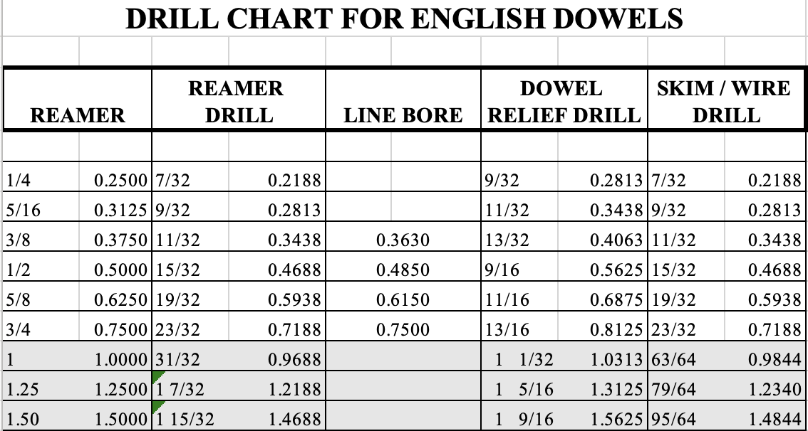
Reamer Drill | Pre-drill hole for reaming | Leave material for reamer to cut; ensures smooth final hole |
Dowel Relief Drill | Small hole at bottom of dowel hole | Avoids air compression or interference; allows smooth insertion of dowel pin |
Skim / Wire Drill | Hole for wire EDM or skim cut | Enables EDM wire to enter or skim cut to reach the surface; pre-hole for precision cutting |
Counter Bore | Enlarged top portion of a hole | Allows bolt head (usually socket or hex) to sit flush; ensures assembly surface is flat |
Countersink | Conical hole for flat-head screws | Bolt head sits flush; compatible with flat-head screws |
Clearance Hole | Hole slightly larger than bolt | Allows free bolt passage; no tight fit |
Key Concept: Many of these names are purpose-driven, not literal English. For example:
- “Reamer Drill” → Drill for reaming (not drilling with a reamer).
- “Relief Drill” → Drill for relief / clearance.
- “Wire Drill / Skim” → Drill for EDM wire / skim-cut pre-hole.
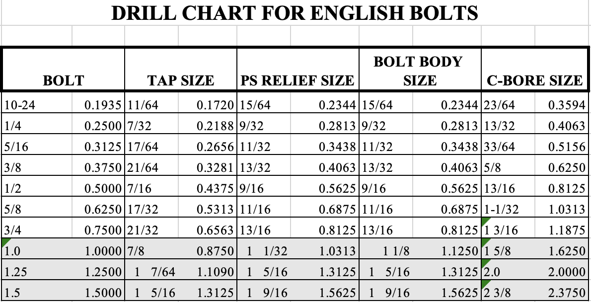
4. Typical Hole Machining Workflow for a Dowel Pin (1/4 inch example)
- Pre-Drill: Use Reamer Drill size (e.g., 0.2188 in)
- Line Bore (optional): Correct coaxiality if multiple holes
- Reaming: Use 1/4 in reamer for final precise hole
- Dowel Relief Drill: Drill a small hole at bottom (e.g., 9/32 in)
- Wire EDM / Skim Drill: Optional, pre-hole for precision wire EDM cuts
5. Understanding English Terminology Logic
Many mechanical terms are function-oriented, not literal:
Word | Mechanical Meaning | Language Insight |
Drill | Create hole | Literal English matches action |
Bore | Expand/correct existing hole | “Bore” = enlarge / make hole |
Ream | Precision finish hole | Very fine cutting; final diameter |
Honing | Ultra-fine finish | “Hone” = polish, refine |
Relief | Avoid interference | Like “pain relief” = release |
Counter | Enlarged or opposite portion | E.g., counter bore = enlarge for bolt head |
Wire | Wire EDM | Industry shorthand; not electric wire |
Skim | Light cut | Just scrape / lightly remove material |
Line | Coaxial axis | Not a thread; ensures multiple holes align |
6. Practical Advice for Business Professionals
- Dowels ≠ Bolts: Dowels for alignment, bolts for fastening.
- Hole dimensions in charts are guidelines for machining sequence: pre-drill → bore → ream → optional EDM/skim.
- Terminology is functional, not literal English; focus on “why this hole/tool exists”.
- Ask engineers about tolerance and precision; charts tell what is needed for assembly, not just the number.
- Counterbore vs Countersink: Check if bolt head should sit flush; affects assembly and surface contact.
- Wire EDM and Skim Cut: Not the same; skim cut is the precision finish step within wire EDM.
7. Summary Diagram (Conceptual Workflow)
Drill (pre-hole)
↓
Bore (align, adjust diameter & coaxiality)
↓
Ream (precision diameter & smooth wall)
↓
Relief Drill (optional, avoid bottom interference)
↓
Wire EDM / Skim Cut (optional, precision cutting)
↓
Insert Dowel or Bolt
Key Insight: Each column in your machining charts corresponds to a stage in the hole preparation and assembly process, with specific tools and sizes to achieve alignment, precision, and proper fit.
✅ Conclusion
Understanding dowels, bolts, and machining terminology is not about memorizing translations. It’s about:
- Knowing the function of each fastener and hole.
- Understanding why each machining step exists (drill → bore → ream → skim/hone).
- Being able to interpret technical charts and communicate with engineers confidently.
For business personnel in mold, mechanical, and fixture industries, grasping this logic allows better client communication, more informed quotes, and accurate interpretation of technical specifications.