Why Wall Thickness Matters in Plastic Injection Molding

Understanding Hot Mass, Cooling Behavior, and Proper Boss Design
Introduction: Small Design Details Can Make a Big Difference
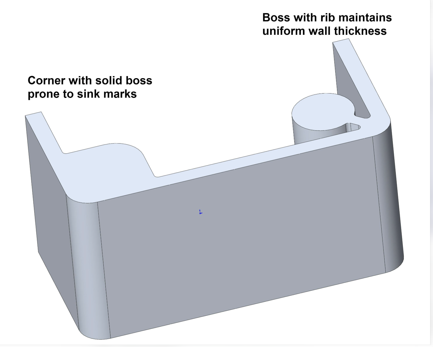
In plastic injection molding, product design is not simply about creating the required shape.
Every design decision can affect how plastic flows into the mold, how the part cools, how much it shrinks, and whether the final product meets its appearance and mechanical requirements.
One of the most important design considerations is wall thickness.
A plastic part with uneven wall thickness may experience different cooling rates in different areas. This can lead to sink marks, internal voids, warpage, dimensional changes, and longer production cycle times.
A typical example is a screw boss.
A boss may look like a small and simple feature, but if it contains too much material or is not properly designed, it can create local thick sections and cooling problems.
In this article, we will explore why wall thickness matters, what engineers mean by Hot Mass and Smaller Hot Mass, and how to design a screw boss that balances manufacturability, appearance, and mechanical strength.
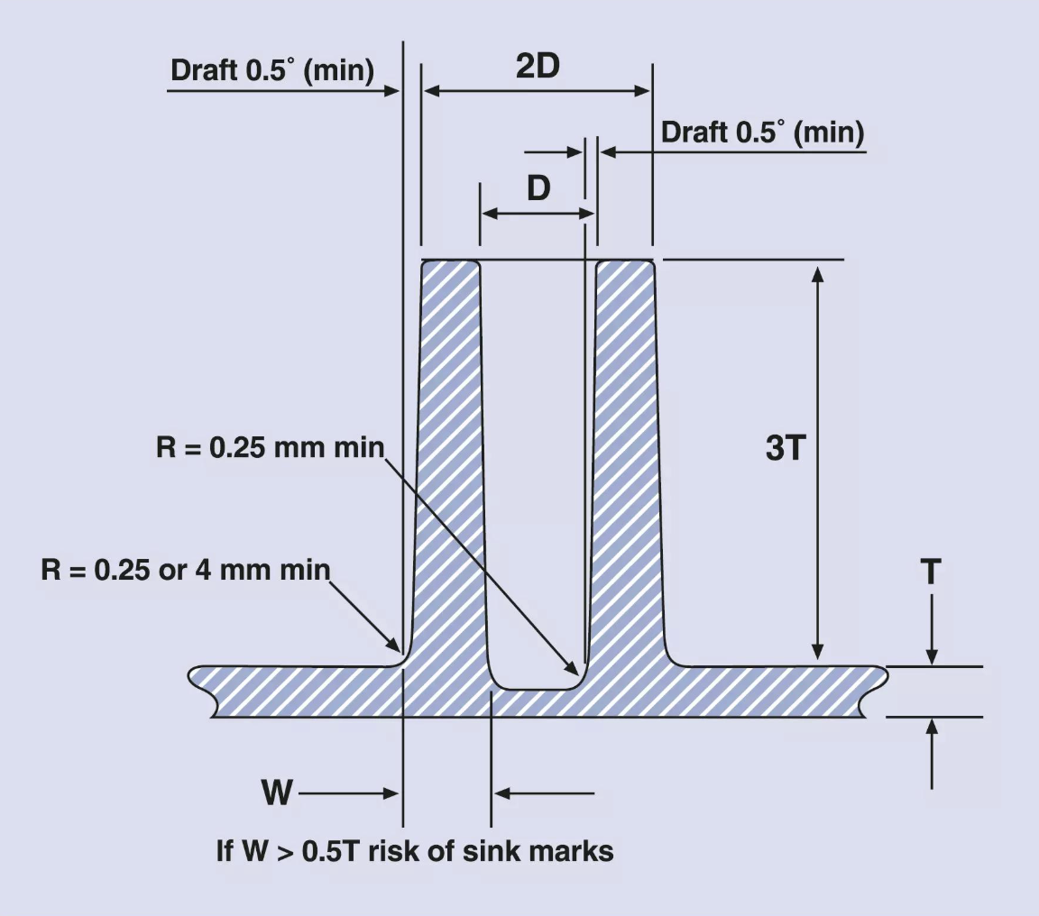
1. Why Should Plastic Wall Thickness Not Be Designed Randomly?
One of the basic principles of plastic product design is to maintain relatively uniform wall thickness whenever possible.
Why?
Because plastic needs to cool and shrink after it is injected into the mold.
When the wall thickness is relatively uniform, different areas of the product generally have more consistent cooling and shrinkage behavior.
However, when a product contains thick and thin sections, the cooling process becomes less uniform.
Consider a simple example:
·
Main product wall thickness: 2.0 mm
·
·
Local boss wall thickness: 2.5 mm
·
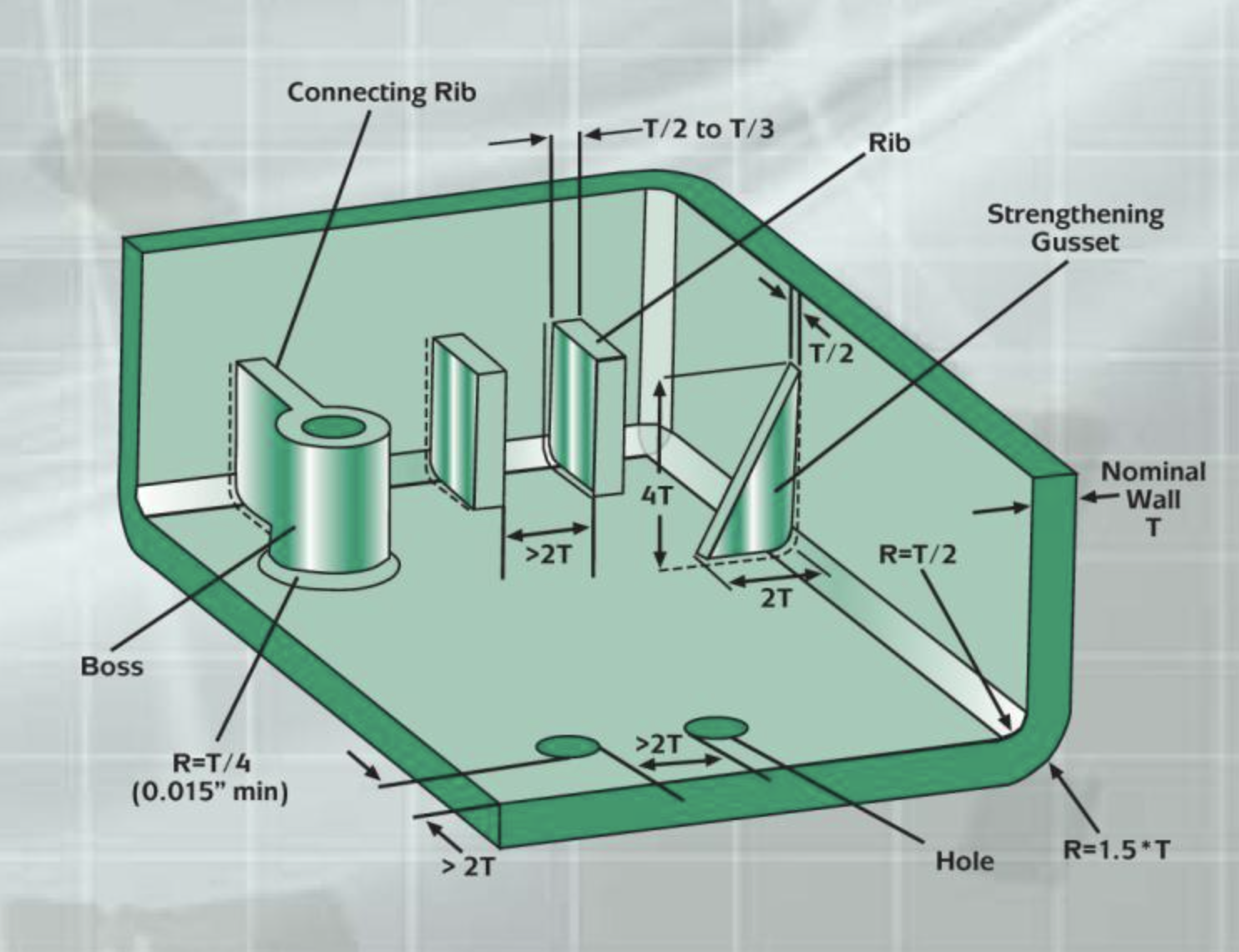
Although the difference is only 0.5 mm, the thicker area may take considerably longer to cool.
The thicker section contains more material and may have a longer heat transfer distance. As a result, its internal temperature may remain higher even after the surrounding thinner sections have started to solidify.
This difference can lead to several potential problems:
Sink Marks
Sink marks are small depressions or visible marks on the surface of a molded part.
They often occur when the material inside a thick section continues to shrink after the outer surface has already become solid.
If sufficient material cannot be supplied during the packing stage, the surface may be pulled inward.
Internal Voids
Voids are empty spaces that can form inside thick plastic sections when the material shrinks and the internal volume cannot be sufficiently compensated.
Warpage
Uneven cooling and shrinkage can cause different areas of a plastic part to contract by different amounts, resulting in deformation.
Longer Cooling Time
Thicker sections generally require more time to cool sufficiently before the part can be ejected.
This can increase the overall production cycle time.
The key principle is simple:
Uniform wall thickness helps achieve more consistent cooling, shrinkage, and dimensional stability.
This does not mean that every part must have exactly the same wall thickness. Ribs, bosses, clips, and other functional features are often necessary. The goal is to design these features without creating unnecessary material accumulation.
2. Understanding the Relationship Between Wall Thickness and Cooling Time
To understand why thick sections can create problems, we need to look at a basic heat transfer principle.
During injection molding, molten plastic enters the mold cavity at a relatively high temperature.
The mold is usually maintained at a much lower temperature. Heat therefore transfers from the plastic into the mold steel and is eventually removed through the cooling system.
The heat inside the plastic does not disappear immediately. It gradually moves from the hotter internal areas toward the cooler mold surfaces.
This process is called heat conduction. Real cooling behavior also depends on:
·
Plastic material properties
·
·
Mold temperature
·
·
Cooling channel location and efficiency
·
·
Part geometry
·
·
Thermal contact between plastic and mold steel
·
·
Required ejection temperature
·
·
Crystallization behavior in semi-crystalline materials
·
The main lesson is that even a relatively small increase in wall thickness can have a significant effect on cooling behavior.
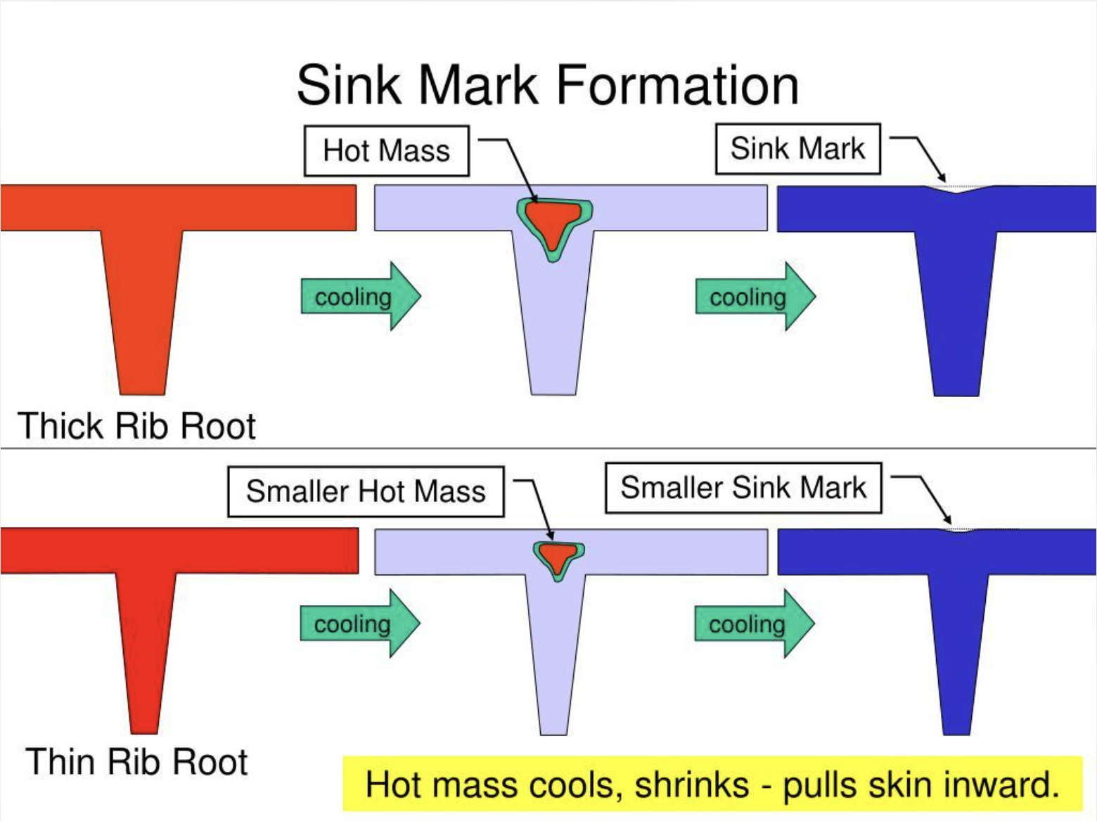
3. What Is Hot Mass in Injection Molding?
The term Hot Mass is sometimes used by mold designers and injection molding engineers to describe a local area where too much plastic material is concentrated.
It is commonly associated with thick sections, material accumulation, and areas that retain heat longer than surrounding thinner sections.
It is useful to understand the term through a simple example.
Imagine a plastic housing with a uniform 2.0 mm wall.
Now imagine adding a thick boss to the back of the housing.
If the boss root is designed with too much solid material, the area where the boss connects to the main wall may become significantly thicker than the surrounding structure.
This creates a local material concentration.
The thicker area may:
·
Contain more material that needs to cool
·
·
Have a longer heat transfer distance
·
·
Remain hot longer than nearby thin sections
·
·
Experience different shrinkage behavior
·
Engineers may describe this area as a Hot Mass.
In simpler words:
Hot Mass refers to an area with excessive local material accumulation that can create cooling and shrinkage challenges.
A useful distinction:
Hot Mass is an informal engineering expression rather than a precisely defined physical quantity. It should not be confused with Thermal Mass, which is a physical concept describing the ability of an object to store heat.
Why Is Hot Mass a Problem?
The main concern is not simply that the product becomes heavier.
The real issue is the local concentration of plastic material.
When a thick area cools more slowly than the surrounding wall, the material inside may continue to shrink after the outer surface has become solid.
This can result in sink marks or internal voids.
Therefore, engineers try to avoid unnecessary Hot Mass during the product design and DFM review stages.
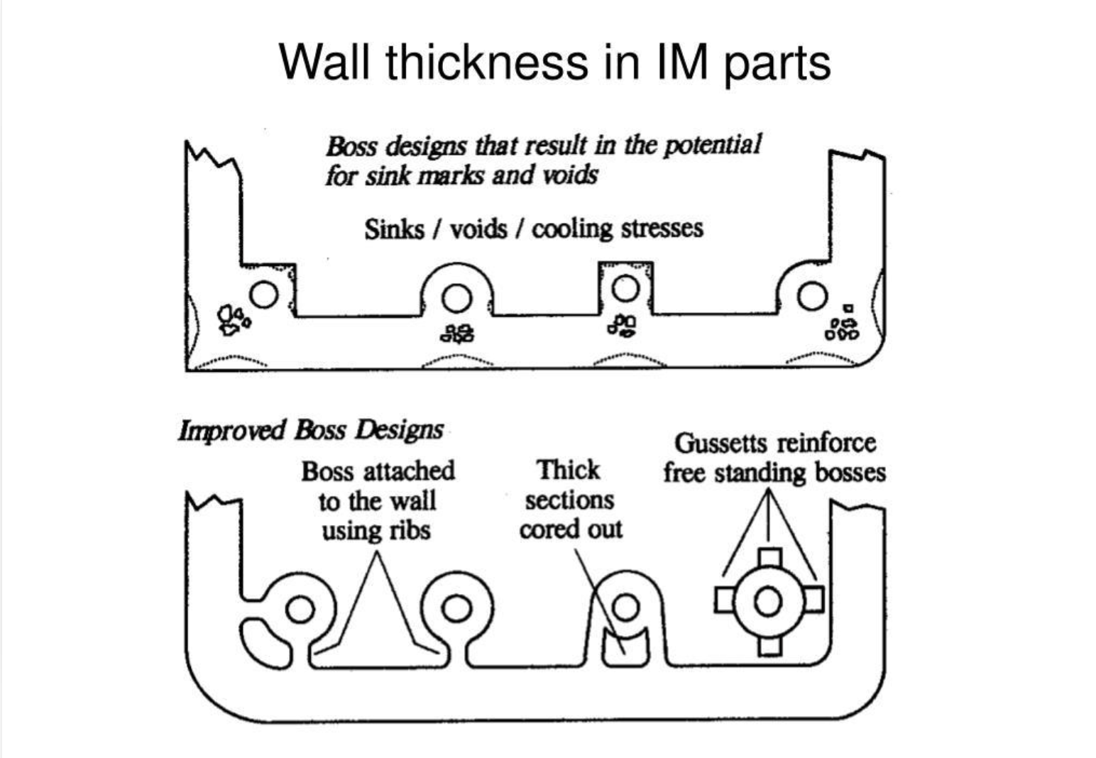
4. What Does Smaller Hot Mass Mean?
When an engineer says:
"We should reduce the Hot Mass around this boss."
The intention is usually to reduce unnecessary material accumulation and improve the cooling behavior of that area.
This is sometimes described as Reducing Hot Mass or Creating a Smaller Hot Mass.
There are several ways to achieve this.
4.1 Coring – Removing Unnecessary Material
Coring means removing unnecessary material from a thick section.
Instead of designing a solid and thick connection between a boss and the main wall, engineers may create a hollow or reduced-material structure.
This helps reduce local material accumulation.
4.2 Optimizing Wall Thickness
The boss wall and the connection between the boss and the main wall should be reviewed carefully.
The aim is to avoid excessive thickness while maintaining sufficient strength.
4.3 Using Ribs or Gussets
Rather than increasing the entire wall thickness, engineers can use ribs or gussets to provide structural support.
These features can improve stiffness and mechanical strength with less additional material than a solid thick section.
However, ribs and gussets must also be designed carefully. If they are too thick or too numerous, they can create new thick sections and sink mark risks.
An Important Design Principle
Reducing Hot Mass does not mean making every section as thin as possible.
The goal is to remove unnecessary material while maintaining:
·
Mechanical strength
·
·
Screw retention
·
·
Dimensional stability
·
·
Product functionality
·
·
Moldability
·
Good plastic design is always a balance between material efficiency and structural performance.
5. Understanding Boss Design in Injection Molding
A boss is a raised cylindrical or similar structural feature in a plastic component.
It is commonly used for:
·
Screw fastening
·
·
PCB mounting
·
·
Component positioning
·
·
Assembly support
·
·
Mechanical connections
·
A screw boss must provide enough material to hold the screw securely.
However, adding too much material can create local cooling problems.
This creates an important design challenge:
How can we design a boss that is strong enough for assembly without creating excessive material accumulation?
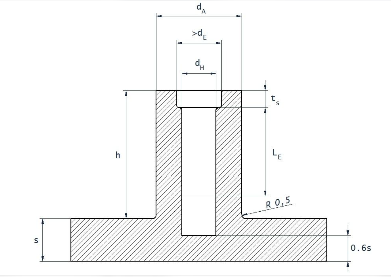
5.1 Boss Wall Thickness
Boss wall thickness is one of the first dimensions engineers should review.
Consider the following example:
·
Main wall thickness: 2.0 mm
·
·
Boss outer diameter: 8.0 mm
·
·
Boss inner diameter: 3.0 mm
·
The radial boss wall thickness is:
[
(8.0-3.0)/2=2.5\text{ mm}
]
The boss wall is thicker than the main product wall.
This does not automatically mean the design is unacceptable. The suitability depends on the plastic material, screw type, mechanical load, boss geometry, and appearance requirements.
Engineers should review whether the boss can be redesigned with less material while maintaining the required screw-holding performance.
5.2 Boss Root Design
The boss root is the area where the boss connects to the main product wall.
This area deserves particular attention because material can accumulate around the connection.
A poorly designed boss root may create a thick section that cools more slowly and increases the risk of sink marks on the opposite surface.
Possible improvements include:
·
Reducing unnecessary material at the boss root
·
·
Using a suitable transition radius
·
·
Introducing coring where appropriate
·
·
Adding properly designed ribs or gussets
·
The design should avoid abrupt changes in wall thickness wherever possible.
5.3 Rib and Gusset Design
A rib is a thin reinforcing feature used to improve the stiffness of a plastic part.
A gusset is usually an angled or triangular reinforcing feature that supports a boss or wall.
Both features can improve mechanical strength without requiring the entire structure to become thicker.
For example, a boss may be supported by two or three gussets connecting it to the main wall.
This can improve resistance to bending and movement during screw tightening or product use.
However, ribs and gussets should not be excessively thick.
If they create another large material concentration, they may introduce sink marks and cooling problems.
Therefore, their thickness, height, length, draft angle, and position should be reviewed during DFM.
6. Why Should Boss Design Follow the Screw Manufacturer's Recommendations?
This is another important point that is sometimes overlooked during plastic product design.
A boss is not designed only according to the plastic material. It must also work with the screw that will be installed in it.
Different screws have different mechanical requirements.
For example:
·
Self-tapping screws
·
·
Thread-forming screws
·
·
Thread-cutting screws
·
·
Machine screws with metal inserts
·
Each type may require different boss dimensions and installation conditions.
This is why engineers should refer to the screw manufacturer's design recommendations.
The recommendations may include:
Pilot Hole Diameter
The pilot hole is the initial hole in the plastic boss before screw installation.
If the hole is too small, installation torque may become too high, increasing the risk of boss cracking.
If the hole is too large, the screw may not achieve sufficient thread engagement and holding strength.
Boss Outer Diameter
The boss needs sufficient surrounding material to resist the forces generated during screw installation and use.
Thread Engagement Length
The screw needs enough engagement with the plastic to achieve the required holding strength.
Installation Torque
The recommended tightening torque helps prevent over-tightening and damage to the plastic boss.
Material Compatibility
The screw design should be suitable for the selected plastic material, including its stiffness, strength, and reinforcement level.
Why Is This Important?
A boss that looks strong may still fail during screw installation.
For example:
·
An undersized pilot hole may cause excessive installation torque.
·
·
An oversized pilot hole may lead to poor screw retention.
·
·
Insufficient engagement length may cause the screw to pull out.
·
·
Excessive tightening torque may crack the boss.
·
Therefore, the boss and the screw should be treated as one fastening system rather than two independent components.
A good engineering practice is to obtain the screw manufacturer's design guidelines and verify the design through testing under the actual material and assembly conditions.
7. How Do Injection Pressure and Holding Pressure Affect the Problem?
Wall thickness and boss geometry are mainly product design considerations, but the injection molding process also plays an important role.
Two terms are particularly important:
Injection Pressure
Injection pressure is the pressure used to push molten plastic into the mold cavity during the filling stage.
Its main purpose is to fill the cavity before the material becomes too cold to flow.
Holding Pressure / Packing Pressure
After the cavity has been filled, holding pressure is applied to compensate for material shrinkage.
As plastic cools, its volume generally decreases.
Holding pressure helps push additional molten material into the cavity through the gate, compensating for this shrinkage while the gate remains open.
If the holding pressure is insufficient, or the holding time is too short, the part may not receive enough additional material to compensate for shrinkage.
This can increase the risk of sink marks or internal voids.
However, increasing holding pressure is not always the correct solution.
Excessive holding pressure may cause other problems, such as flash, excessive residual stress, or difficulty in demolding.
The gate location, gate size, gate freezing time, and part geometry must also be considered.
Most importantly, process optimization cannot always correct a fundamentally poor product design.
If a boss creates excessive material accumulation, improving the geometry may be a more effective long-term solution than simply adjusting machine parameters.
8. A Practical DFM Checklist for Boss Design
During a design review, engineers can use the following checklist.
Inspection item | Key question |
Main wall thickness | Is the wall thickness relatively uniform? |
Boss wall thickness | Is there unnecessary material around the boss? |
Boss root | Is there excessive material accumulation at the connection? |
Coring | Can unnecessary material be removed? |
Ribs and gussets | Can structural support be improved without creating thick sections? |
Screw type | Is the boss suitable for the selected screw? |
Pilot hole | Does the hole follow the screw manufacturer's recommendation? |
Engagement length | Is there sufficient thread engagement? |
Tightening torque | Can the boss withstand the required assembly torque? |
Appearance | Could sink marks be visible on the opposite surface? |
Cooling | Are the cooling channels suitable for the local geometry? |
Testing | Has the design been verified through molding and assembly tests? |
The final design should be evaluated based on the actual application, plastic material, mold structure, and assembly requirements.
9. Final Thoughts: Good Design Starts Before Mold Manufacturing
A successful injection molding project does not begin when the mold enters the machining workshop.
It begins much earlier, during product design and DFM evaluation.
A small feature such as a screw boss can influence cooling behavior, shrinkage, product appearance, mechanical performance, and production efficiency.
Understanding wall thickness, Hot Mass, Coring, Ribs, Gussets, and screw design requirements helps engineers identify potential problems before the mold is manufactured.
For manufacturers, early design optimization can reduce mold modifications, shorten development time, and improve production stability.
For product designers, it helps create components that are easier to manufacture and more reliable in real applications.
The most important lesson is this: A good plastic design is not about adding more material to make a part stronger. It is about placing the right amount of material in the right locations to achieve the required performance while maintaining good moldability.
At Opro-Tech, we believe that better manufacturing starts with better engineering decisions.