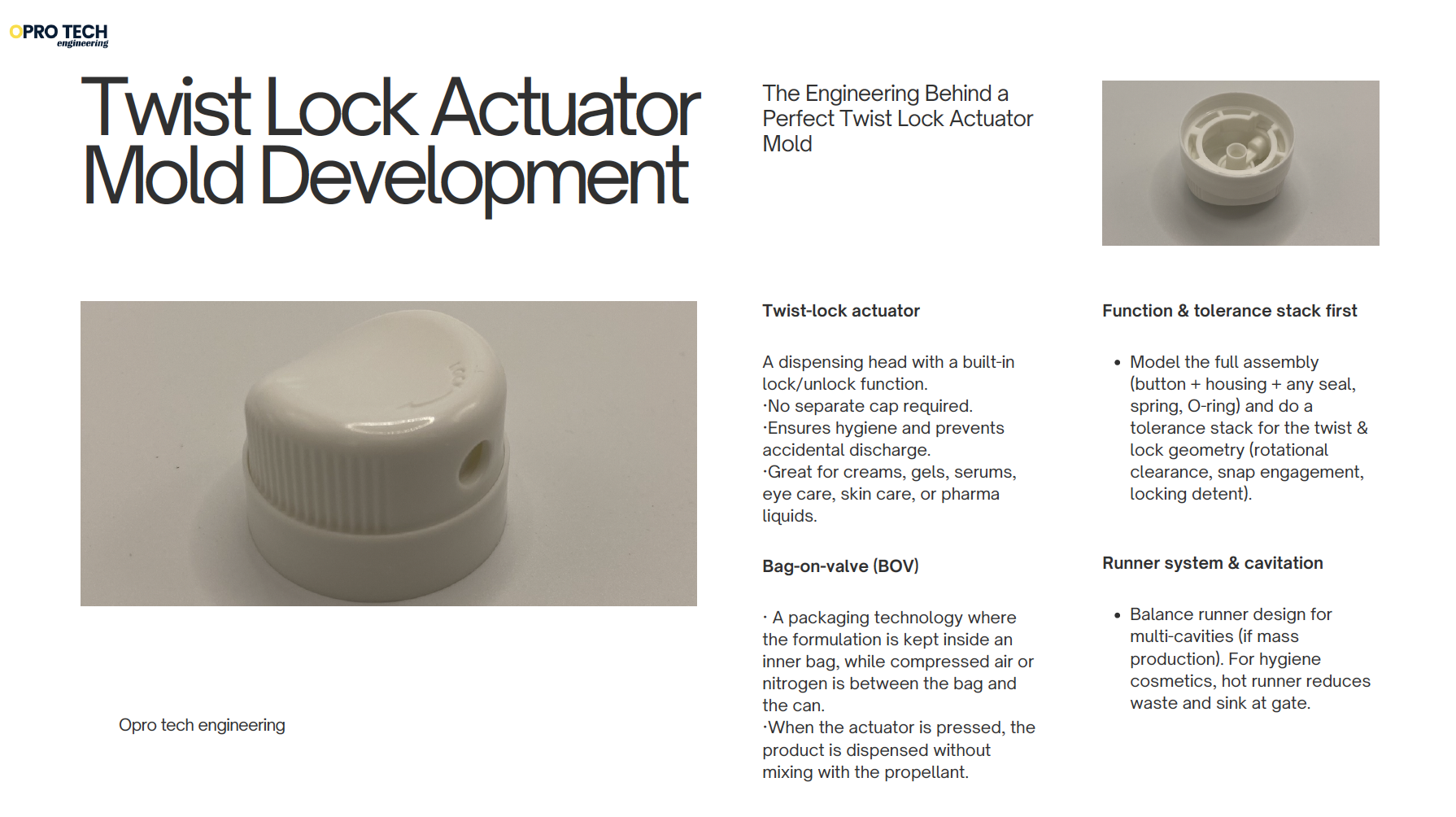
A Practical Guide to Twist Lock Actuator Mold Development

In the fast-evolving world of smart packaging, the twist-lock actuator has quickly become a symbol of both hygiene and convenience. Unlike traditional dispensers that rely on removable caps, this clever design allows users to simply twist and lock the actuator to open or close, eliminating the need for a separate cap and reducing contamination risks. Its sleek, functional mechanism has made it a preferred choice in eye care, skincare, and pharmaceutical applications.
For those of us in the tooling and mold industry, developing molds for such precise and dynamic parts presents both a challenge and an opportunity—to bring design innovation and high-precision molding together in a single, elegant solution.
Firstly, let’s get to know what is a twist-lock actuator dispensing system?
It’s basically a smart dispenser that replaces the traditional bottle + separate cap. Instead of removing a cap, the actuator head twists to “lock” or “unlock” the dispensing function.
✨ Key points about it:
· Hygiene: Since you don’t have to remove and handle a cap, there’s less contamination risk. That’s why it’s widely used in eye care, skin care, and pharmaceuticals.
· Convenience: One-hand operation, no cap to lose, travel-friendly.
· Safety: Locking mechanism prevents accidental leaks/spills (important for liquids, gels, serums).
· Design: Usually sleek, modern, considered a “premium packaging” solution.
We often see the twist-lock actuator and the bag-on-valve (BOV) system in eye drops, facial serums, creams, hand sanitizers, and even some oral care or medical topical solutions.
Here’s how they relate:
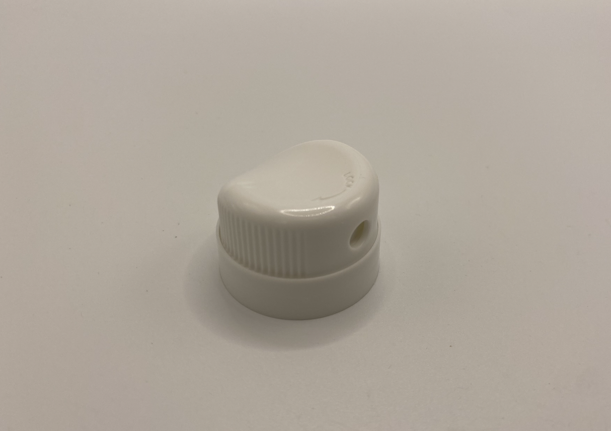
🔹 Twist-lock actuator
· A dispensing head with a built-in lock/unlock function.
· No separate cap required.
· Ensures hygiene and prevents accidental discharge.
· Great for creams, gels, serums, eye care, skin care, or pharma liquids.
🔹 Bag-on-valve (BOV)
· A packaging technology where the formulation is kept inside an inner bag, while compressed air or nitrogen is between the bag and the can.
· When the actuator is pressed, the product is dispensed without mixing with the propellant.
· Benefits:
o 360° spraying (works upside down too).
o Longer shelf life (product isolated from air).
o Hygienic and consistent dosing.
o Eco-friendly (often uses air or nitrogen instead of harmful propellants).
· Applications: wound sprays, nasal sprays, sunscreens, lotions, and sensitive skincare.
👉 When paired together:
· A BOV can filled with sterile product + a twist-lock actuator gives a cap-less, hygienic, safe, and premium dispensing solution, especially valued in medical, eye care, and high-end cosmetic products.
Now that we understand what a twist-lock actuator is and why it’s gaining popularity, the next question is — how do we bring such a precise, functional concept to life through tooling?
Behind its simple “twist and lock” motion lies a surprisingly complex structure: moving parts, tight tolerances, and intricate undercuts that demand both technical insight and tooling finesse.
Developing molds for these actuators isn’t just about achieving a clean appearance — it’s about ensuring smooth rotation, consistent locking force, and reliable sealing over thousands of cycles.
In the next section, we’ll look at the key technical points mold makers must pay attention to when developing a tooling mold for twist-lock actuator components.
Below We’ve put together a focused, practical checklist and explanation of the key technical issues to watch for when developing injection tooling for a twist-lock actuator (button + housing) used in hygiene-sensitive markets (eye care / skin care / pharma). We’ll include recommended starting numbers where helpful, but will also flag where you must validate by material datasheet / prototype.
What to get right (top priorities)
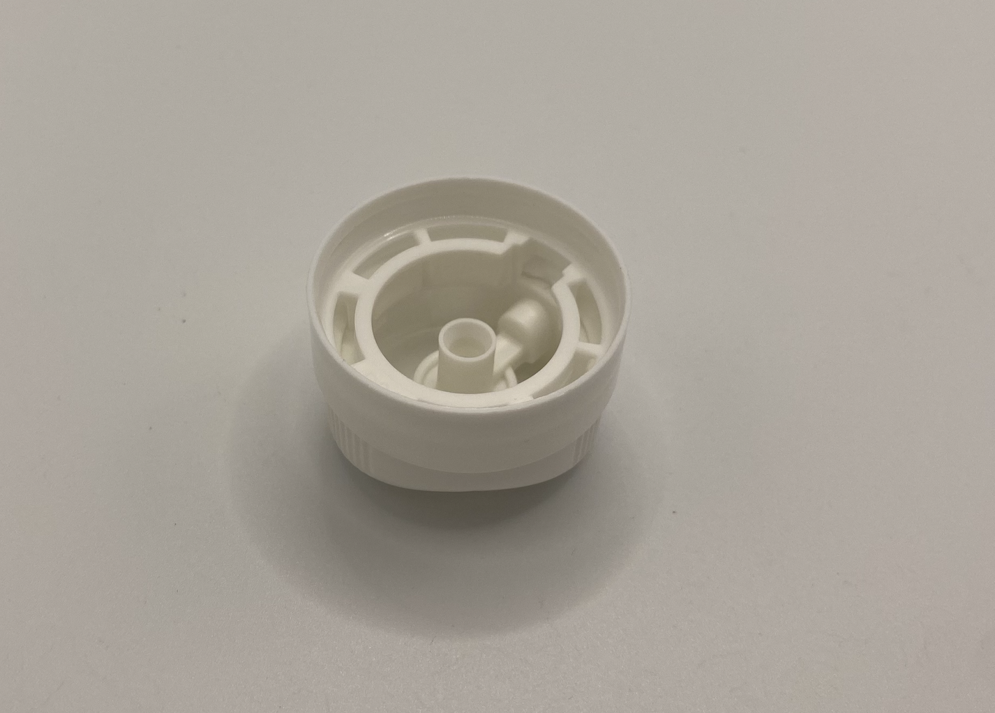
- Function & tolerance stack first
- Model the full assembly (button + housing + any seal, spring, O-ring) and do a tolerance stack for the twist & lock geometry (rotational clearance, snap engagement, locking detent).
- Target the fit type (rotating clearance vs interference) early: rotating parts usually need 0.05–0.20 mm radial clearance depending on material and surface finish — verify with material thermal expansion and shrinkage.
- Material selection
- Medical / eye-care often require USP Class VI / biocompatible grades, low extractables. Common choices:
- PP / PP copolymer — cheap, good sliding, flexible snaps.
- POM (acetal) — great for low friction, dimensional stability, precision moving parts.
- PE / HDPE — simple, flexible.
- Engineering plastics (PBT, PC, ABS) — if higher stiffness/clarity needed.
- LSR (liquid silicone) for seals/soft parts.
- Check chemical compatibility (active ingredients, alcohol, preservatives), sterilization method, pigmentation, and migration.
- Mating geometry & snap/locking details
- Design clear, reproducible locking features: chamfers, lead-ins, fillets on locking shoulders to avoid stress concentrations.
- Avoid tiny radii in load paths; add radii ≥0.5 mm where possible.
- Specify required insertion/rotation torque and retention force and validate with 1st article testing.
- Wall thickness, ribs, bosses
- Keep wall thickness uniform. Typical thin-walled actuator parts: 0.6–2.0 mm (choose based on material).
- Use ribs/bosses sized per material (boss base thickness ≈ 0.6–0.8× nominal wall).
- Avoid deep boss/hollow without proper coring—risk of sink.
- Draft & parting line
- Provide draft on all vertical surfaces: 0.5°–2° depending on texture and depth (textured surfaces need more draft).
- Place the parting line to minimize visible flash on cosmetic areas and to keep locking edges and thread/rail features accurate.
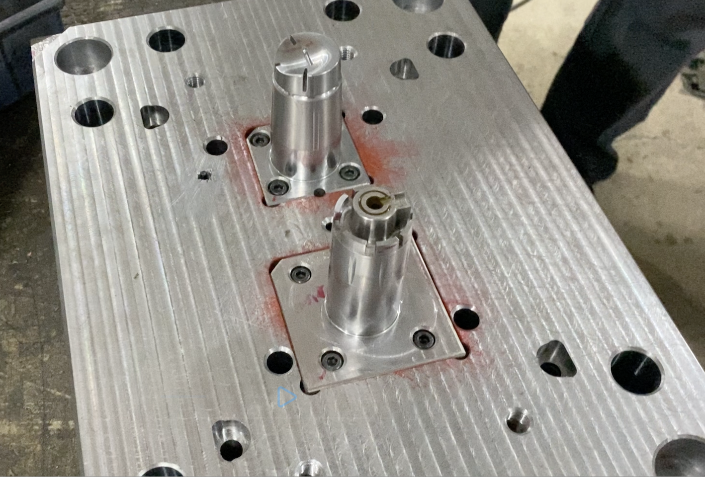
- Undercuts & side actions
- Twist-lock geometries often require undercuts, internal features or internal threads. Use:
- slides / lifters / side-action cams, or
- collapsible cores for internal threads, or
- unscrewing mechanisms if internal screw features are present.
- Consider complexity vs cost: slides add mold complexity and maintenance; collapsible cores add cost but give clean internal threads.
- Gate type & location
- Cosmetic/hygienic products usually avoid visible gate scars on functional mating surfaces.
- Preferred: valve-gated hot runner (tip gate/valve gate) or submarine (tunnel) gate placed on non-visible area.
- If small single cavities, a micro pin gate or edge gate may be acceptable — but expect visible vestige.
- Runner system & cavitation
- Balance runner design for multi-cavities (if mass production). For hygiene cosmetics, hot runner reduces waste and sink at gate.
- Consider valve-gated manifold for better aesthetics and gating control.
- Venting & flow issues
- Tiny internal cavities and fine locking features can trap air — provide proper venting (vent grooves or <0.02–0.05 mm vent gaps where necessary).
- Plan vent locations around thin slits/long cores and side-action parts.
- Cooling & cycle time
- Design efficient cooling channels close to thick areas and cores; uniform cooling reduces warpage and shrink differential.
- Copper alloy inserts near hot spots can speed cooling.
- Surface finish & texture
- For hygiene products, smooth, easy-to-clean finishes are best (Ra targets depend on application; cosmetic visible surfaces often polished).
- For better grip, micro textures or soft touch coatings (TPE overmold) are options — allow extra draft and die polishing specs.
- Ejection & part handling
- Ejector pins must not damage functional sealing surfaces — use strips / sleeves / lifters or vacuum pick if required.
- Consider automatically orienting parts for subsequent assembly (press-fit, ultrasonic weld, adhesive).
- Assembly & joining
- Decide joining method in design stage: press-fit snap, ultrasonic welding, heat staking, or adhesives. Tooling features must allow for alignment and fixturing.
- If seals (O-rings) or springs are used, ensure assembly tolerance windows and possible automation tooling.
- Aesthetics vs functionality tradeoffs
- Cosmetic requirements (no gate marks, glossy finish) increase cost (hot runner, valve gates, mirror polish).
- Discuss with client priority: hygiene/functionality vs cost/appearance.
- Tool steel, coatings, corrosion
- For long runs and corrosive environments (e.g., saline/sterile fluids), use corrosion-resistant steel grades and consider nitriding or PVD plating on critical cores.
- Polished cavities for clear parts: hardened steel (e.g., 1.2344 / H13 alternatives); for very high polish use special grades and controlled polishing.
- Quality, validation & regulatory
- For pharma/eye care: consider biocompatibility testing, extractables/leachables, and possible regulatory documentation.
- Plan for process capability studies (Cp/Cpk), dimensional control, life cycle testing, and cleanroom molding if required.
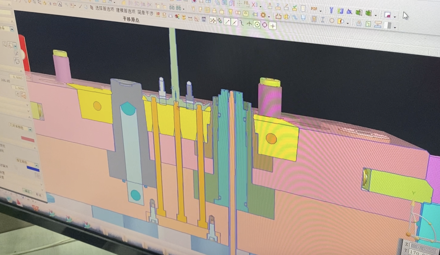
- Prototype & validation
- Moldflow/CAE simulation to check fill, weld lines, pressures, cooling.
- Make soft-tool (prototype) or low-volume insert to validate fit, torque, and sealing before final tooling.
- Maintenance & serviceability
- Complex molds with slides require planned maintenance schedule; design tooling for easy slide/cam access and standard replaceable wear parts.
Recommended numeric starting values (approximate — validate)
· Draft: 0.5°–2° depending on texture.
· Wall thickness: 0.6–2.0 mm typical.
· Rotational clearance (moving radial clearance): 0.05–0.20 mm (material dependent).
· Venting gap: 0.01–0.05 mm (for micro vents).
· Snap engagement deflection: design for appropriate cantilever thickness to achieve required insertion/retention forces; test with physical prototypes.
· Typical shrinkage reference (confirm with resin):
o PP ≈ 1.5–2.5%, POM ≈ 0.2–0.8%, ABS ≈ 0.4–0.8% — always check datasheet.
Process & testing you must plan
· Moldflow analysis early to predict knit lines, filling pressure, and gate location.
· Prototype run: 50–200 parts for assembly, torque, and life tests.
· Cycle-life testing of the twist lock (e.g., 5k–50k cycles depending on spec).
· Leak / sealing test (if dispensing liquid).
· Sterilization compatibility test (if client requires).
· Aging / compatibility test with the actual formula (ensure no swelling, stress cracking, or leachables).
Production & cost tradeoffs
· Hot runner + valve gate → higher mold cost, lower part cost and best aesthetics.
· Slides / collapsible cores → adds complexity and maintenance cost.
· Multi-cavity family mold → lower piece price but more complex balancing and higher risk for first article rejection.
Quick Checklist to hand to your toolmaker / design team
1. Full assembly CAD with all seals/springs.
2. Required torque/retention specs; insertion/rotation force numbers.
3. Material(s) with grade numbers, colorants, biocompatibility needs.
4. Surface finish spec (Ra or polish level), visible area priority.
5. Gate aesthetics preference (valve/hot runner preferred).
6. Expected annual volume (to decide cavitation & steel grade).
7. Sterilization/process compatibility requirements.
8. Required lifecycle (cycles) and environmental tests.
9. Preferred joining/assembly method.
10.Required documentation (IQ/OQ, material certificates, test reports).
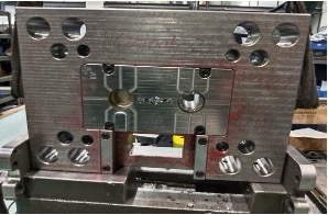
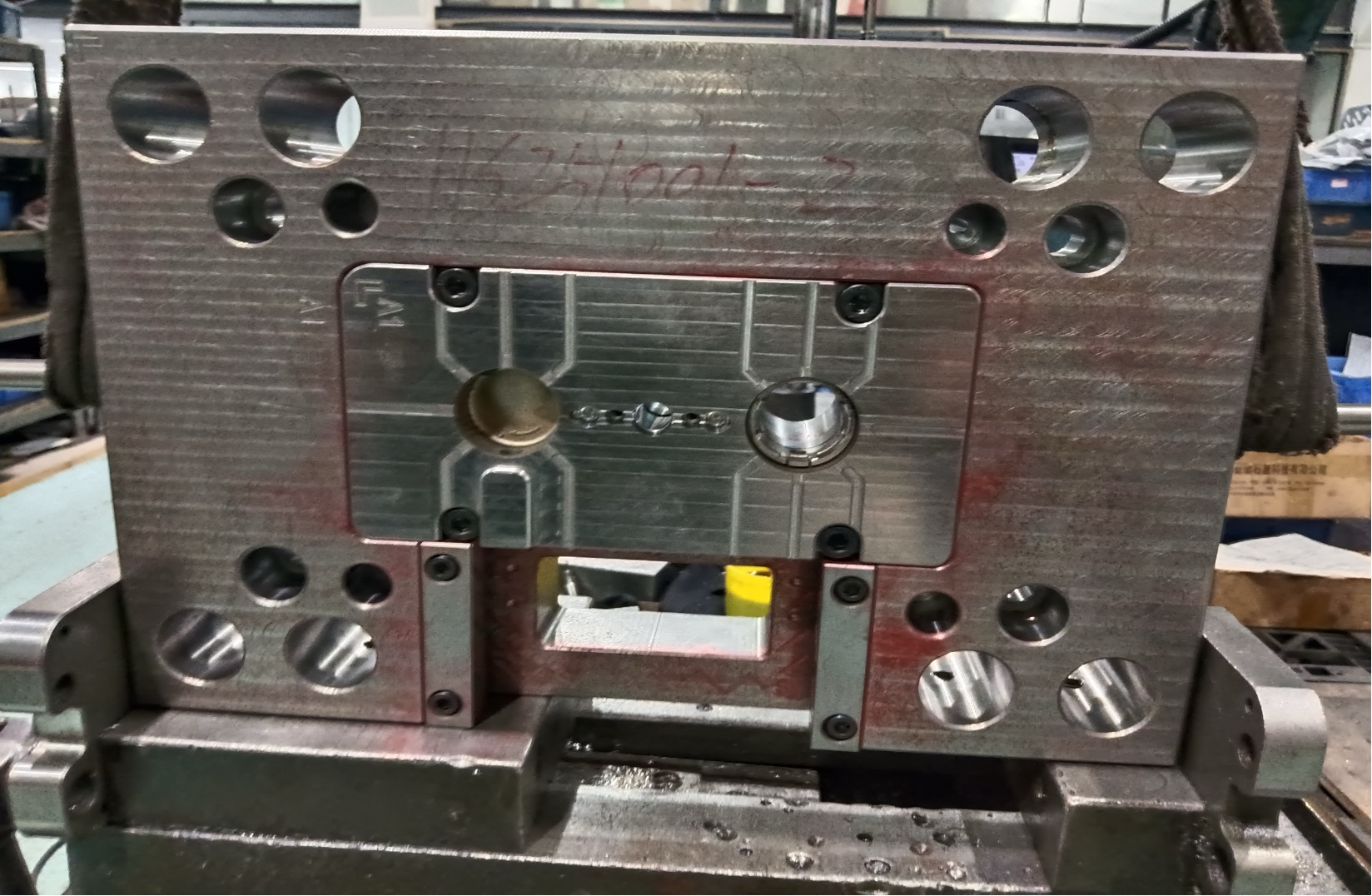
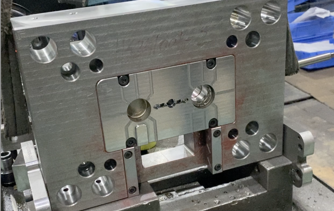
Well another tip, before moving into full-scale production, it’s often wise to take a step back and validate the design with a pilot mold.
For a product as intricate as a twist-lock actuator, a pilot mold allows engineers to test part performance, check assembly fit, and optimize key parameters such as cooling and cycle time.
Once the design and process are proven, the insights gained can be directly applied to the development of the final hot runner production mold — ensuring both precision and efficiency from the very first shot.
In mold manufacturing, stability is not achieved overnight — it’s the result of technical experience, careful process control, and close collaboration between engineers and clients.
From design to validation, every adjustment we make, every test we run, is to ensure the mold performs consistently and efficiently in real production.
Whether it’s optimizing a hot runner system or building a pilot mold for validation, the goal remains the same: to provide reliable, repeatable, and high-quality solutions for our clients.
After all, a stable mold is not just a piece of steel — it’s the foundation of trust and long-term partnership.
Factory add: No 39, Zhen an west road, Changan town , Dong guan city, China.