How do we deal with the undercut in injection tooling molds?
Dealing with undercuts in injection tooling molds involves various techniques and strategies to ensure successful molding of complex parts. Here are some common approaches:
Core Pull Mechanism: Implementing a core pull mechanism allows for the controlled movement of cores within the mold to release undercuts. This mechanism typically involves using hydraulic or mechanical actions to move cores independently from the main mold components.
Side Actions: Incorporating side actions involves adding additional mold components that move laterally to release undercuts. These side actions are often activated by hydraulic or mechanical systems to create the necessary clearance for part ejection.
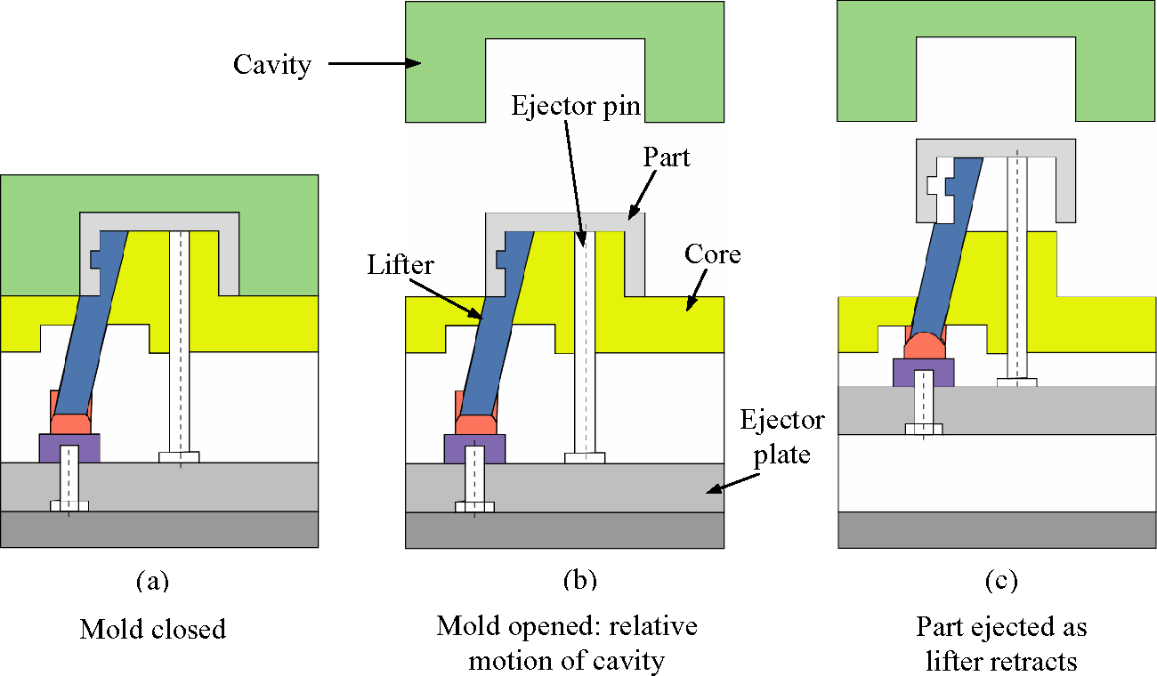
Lifters: Lifters are components within the mold that move perpendicular to the mold's parting line to release undercuts. They can be spring-loaded or mechanically actuated to lift the molded part away from the undercut features during ejection.
Sliders: Sliders are movable components that slide along the mold's parting line to release undercuts. They are often guided by precision mechanisms and can be activated using hydraulic or mechanical systems.
Core Pins: Utilizing collapsible or expandable core pins allows for the creation of complex internal features within the molded part. These pins can retract or expand within the mold cavity to accommodate undercuts during part ejection.
Mold Inserts: Incorporating removable mold inserts with intricate features can help to address specific undercut areas. These inserts can be designed to release from the molded part or the mold itself to facilitate part ejection.
EDM (Electrical Discharge Machining): Employing EDM to create the mold cavity allows for the precise formation of intricate features, including undercuts. This method enables the production of molds with highly complex geometries to accommodate undercuts.
By employing these techniques and technologies, manufacturers can effectively address undercuts in injection tooling molds, enabling the production of intricate and precise molded parts.
To get more other mechanism please keep reading as below.
一,A spring loaded lifter
A spring-loaded lifter in a tooling mold is a type of mechanism designed to assist in the ejection of undercut features or complex shapes from the mold cavity. It consists of a lifter component attached to a spring mechanism, which allows the lifter to move up and down within the mold.

The advantages of using spring-loaded lifters in tooling molds include :
1, Ejection of Undercuts: Spring-loaded lifters are particularly useful for ejecting parts with undercuts or complex geometries that cannot be released using traditional ejector pins alone.
2, Improved Mold Release: The spring mechanism provides additional force to overcome friction between the part and the mold cavity, ensuring smoother and more reliable ejection.
3, Reduced Wear and Tear: By distributing the ejection force more evenly across the part surface, spring-loaded lifters help minimize wear and tear on the mold components, extending their lifespan.
4, Enhanced Design Flexibility: Spring-loaded lifters enable designers to create more intricate and complex part geometries without compromising moldability, allowing for greater design flexibility.
5, Increased Production Efficiency: By facilitating the ejection of challenging parts, spring-loaded lifters help reduce the risk of production delays and defects, ultimately improving overall efficiency and productivity.
Overall, the use of spring-loaded lifters in tooling molds can result in smoother production processes, higher quality parts, and greater design freedom.
二,Air ejection
Air ejection in tooling mold refers to the process of using compressed air to forcefully eject the molded part from the mold cavity once it has been formed. This mechanism is typically achieved using air channels or passages strategically integrated into the mold design.
The primary purpose of air ejection is to facilitate the removal of the molded part from the mold cavity efficiently and without causing damage to the part or the mold. It helps prevent the part from sticking to the mold surface, which can occur due to vacuum formation or adhesion forces during the molding process. By applying compressed air, the air pressure creates a cushion of air between the molded part and the mold surface, effectively pushing the part out of the cavity.

Air ejection is needed for some designs in tooling molds primarily to facilitate the efficient and reliable ejection of molded parts from the mold cavity. There are several reasons why air ejection may be necessary for specific mold designs:
Complex Geometries: Molded parts with intricate or complex geometries may have undercuts, deep recesses, or intricate details that make it challenging for traditional mechanical ejection methods, such as ejector pins, to release the part from the mold. In such cases, air ejection provides a more effective means of dislodging the part by creating a cushion of air between the part and the mold surface.
Preventing Damage: Some molded parts may be fragile or have delicate features that can be easily damaged if subjected to excessive force during ejection. Air ejection allows for a gentler release of the part, minimizing the risk of deformation, distortion, or breakage.
Enhancing Surface Finish: Mechanical ejection methods like ejector pins can leave marks or blemishes on the surface of the molded part, especially in areas with tight tolerances or cosmetic requirements. Air ejection provides a cleaner and smoother release, helping to preserve the surface finish of the part.
Improving Cycle Time: Air ejection can be faster and more efficient than mechanical ejection methods, particularly for large or complex parts. By utilizing compressed air to eject the part, molders can achieve shorter cycle times and increase overall production efficiency.
Overcoming Vacuum Effect: In some cases, the molded part may create a vacuum seal with the mold cavity, making it difficult to eject using mechanical methods alone. Air ejection helps to break this vacuum seal by introducing pressurized air into the cavity, allowing for easier release of the part.
Overall, air ejection is a valuable tool in tooling mold design, particularly for challenging geometries or demanding molding applications where traditional ejection methods may be insufficient or impractical.
三,Two-stage ejection(Double ejection)
Two-stage ejection in tooling molds is a process where the ejection of a molded part occurs in two distinct stages.
In the first stage, the mold partially ejects the part from the cavity or core. This initial ejection helps to prevent any deformation or damage to the part during the subsequent ejection stage.
In the second stage, the part is fully ejected from the mold cavity or core. This two-stage approach ensures that the part is released smoothly and without any defects.
Two-stage ejection is commonly used in molds where the molded parts have complex shapes or features that may require additional support during ejection to prevent damage. It helps to ensure the integrity of the molded parts and improves the overall quality of the manufacturing process.

https://www.youtube.com/watch?v=_rQWaemMzZA
The application scenarios for two-stage ejection include:
1, Special shapes of finished products. When the shape of the finished product is complex and it is difficult for it to automatically detach after the first ejection, two-stage ejection is required.
2, Products requiring a large partial ejection stroke. For products that are large in size and difficult to completely detach from the mold in one ejection, two-stage ejection can reduce the pressure on the ejector pins, avoiding product damage.
3, Extended molding time requirements for finished products. In some cases, the molding time for finished products is longer, requiring them to remain in the mold for a period of time. This also necessitates the use of two-stage ejection
🚀 Benefits of Two-Stage Ejection:
1️⃣ Enhanced Precision: Achieve impeccable ejection results for intricate designs and large products.
2️⃣ Minimized Risk: Reduce the likelihood of product or mold damage during ejection.
3️⃣ Versatile Application: Suitable for a wide range of molding scenarios, including complex shapes and extended molding times.
四,Accelerated ejectors
Are you seeking to optimize your injection molding process for faster cycle times and improved part quality? Look no further than accelerated ejectors!
Accelerated ejectors are a type of ejector mechanism used in injection molding tooling. They are designed to provide additional force and speed during the ejection phase of the molding process, particularly for parts with deep draws or complex geometries that require more force to be ejected effectively.
The accelerated ejector mechanism typically consists of a set of ejector pins mounted on a movable plate or assembly. These pins are driven by a gear and rack system, where the gear (pinion) rotates and drives the rack, causing the ejector pins to move rapidly and with increased force compared to traditional ejector systems.

The key features and benefits of accelerated ejectors include:
1, Increased ejection force: Accelerated ejectors provide higher ejection forces, which are necessary for ejecting parts with intricate shapes or deep cavities.
2, Faster ejection speed: The gear and rack system enables rapid movement of the ejector pins, resulting in faster ejection cycles and increased productivity.
3, Enhanced part release: The accelerated movement of the ejector pins ensures effective release of molded parts from the mold cavity, reducing the risk of part sticking or deformation.
4, Improved mold longevity: By exerting controlled and consistent force during ejection, accelerated ejectors help minimize wear and tear on the mold components, thereby extending the mold's lifespan.
https://www.youtube.com/watch?v=n5HsmyodaCw
Overall, accelerated ejectors offer a reliable and efficient solution for demanding injection molding applications where high ejection forces and fast cycle times are required.
At #Oprotechengineering, we specialize in integrating cutting-edge ejector systems into injection molding tooling, empowering manufacturers to achieve unparalleled efficiency and performance. Elevate your molding operations with our innovative solutions today!
五,Reverse ejection
Reverse ejection in tooling molds refers to a process where instead of pushing the molded part out of the mold cavity, it is pulled or lifted out from the opposite direction. This technique is often used when conventional ejection methods are not feasible due to part geometry or other design constraints. Reverse ejection can involve mechanisms such as pins, lifters, or slides positioned to extract the part in a direction opposite to the mold opening. It is employed to prevent damage to intricate or delicate features of the molded part during the ejection process.

Reverse ejection is a technique employed in tooling molds to address specific challenges in ejecting molded parts. Here are some key points about reverse ejection:
1, Purpose: Reverse ejection is used when traditional ejection methods, such as ejector pins or plates, are not suitable for removing the molded part from the mold cavity. This may occur due to complex part geometry, undercuts, or delicate features that could be damaged by conventional ejection methods.
2, Mechanism: Reverse ejection involves mechanisms positioned within the mold that act in the opposite direction of the mold opening to extract the molded part. These mechanisms can include retractable pins, lifters, slides, or other specialized components designed to lift or pull the part out of the mold cavity.
3, Implementation: Reverse ejection mechanisms are integrated into the mold design during the tooling stage. Mold designers carefully analyze the part geometry and ejection requirements to determine the most suitable reverse ejection approach. The mechanisms are typically activated either mechanically or hydraulically.
4, Benefits: Reverse ejection allows for the safe and efficient removal of molded parts with complex features or undercuts. By extracting the part from the opposite direction of the mold opening, it minimizes the risk of damage to delicate features and ensures the integrity of the finished part.
5, Applications: Reverse ejection is commonly used in industries where molded parts have intricate designs or challenging geometries, such as automotive, aerospace, consumer electronics, and medical devices. It is especially valuable for components with undercuts or internal features that cannot be accessed using traditional ejection methods.
Overall, reverse ejection is a specialized technique that enhances the efficiency and reliability of the molding process, particularly for complex parts with unique design requirements. It enables manufacturers to produce high-quality molded components while overcoming challenges associated with part ejection.