The Lever Ejection Mechanism: A Cost-Effective Masterpiece for Sequential Demolding

In the competitive landscape of plastic injection molding, achieving perfect part ejection while controlling tooling costs represents a constant balancing act. At Opro tech engineering, we've consistently found that one elegant mechanical solution—the Lever Ejection Mechanism, often called the "Seesaw" or Two-Stage Ejection System—delivers exceptional performance without the complexity and expense of hydraulic alternatives. This article explores why this decades-old mechanical design remains indispensable in modern mold making.
Understanding the Challenge: When Simple Ejection Isn't Enough
Before diving into the solution, let's examine the problem. Many plastic parts present ejection challenges that standard, simultaneous pin ejection cannot solve:
· Deep ribs or bosses creating excessive surface area and vacuum
· Undercuts on the cavity (A-side) requiring that side to release first
· Thin-walled or fragile components prone to deformation
· High-gloss surfaces that cannot tolerate any drag marks
When these conditions exist, forcing the part off in one motion risks damaging the product, the mold, or both. The industry's typical response has been sequential ejection systems, with many immediately considering hydraulic solutions. However, there's a mechanical alternative that often proves superior.
How the Lever Ejection Mechanism Works: Elegant Simplicity
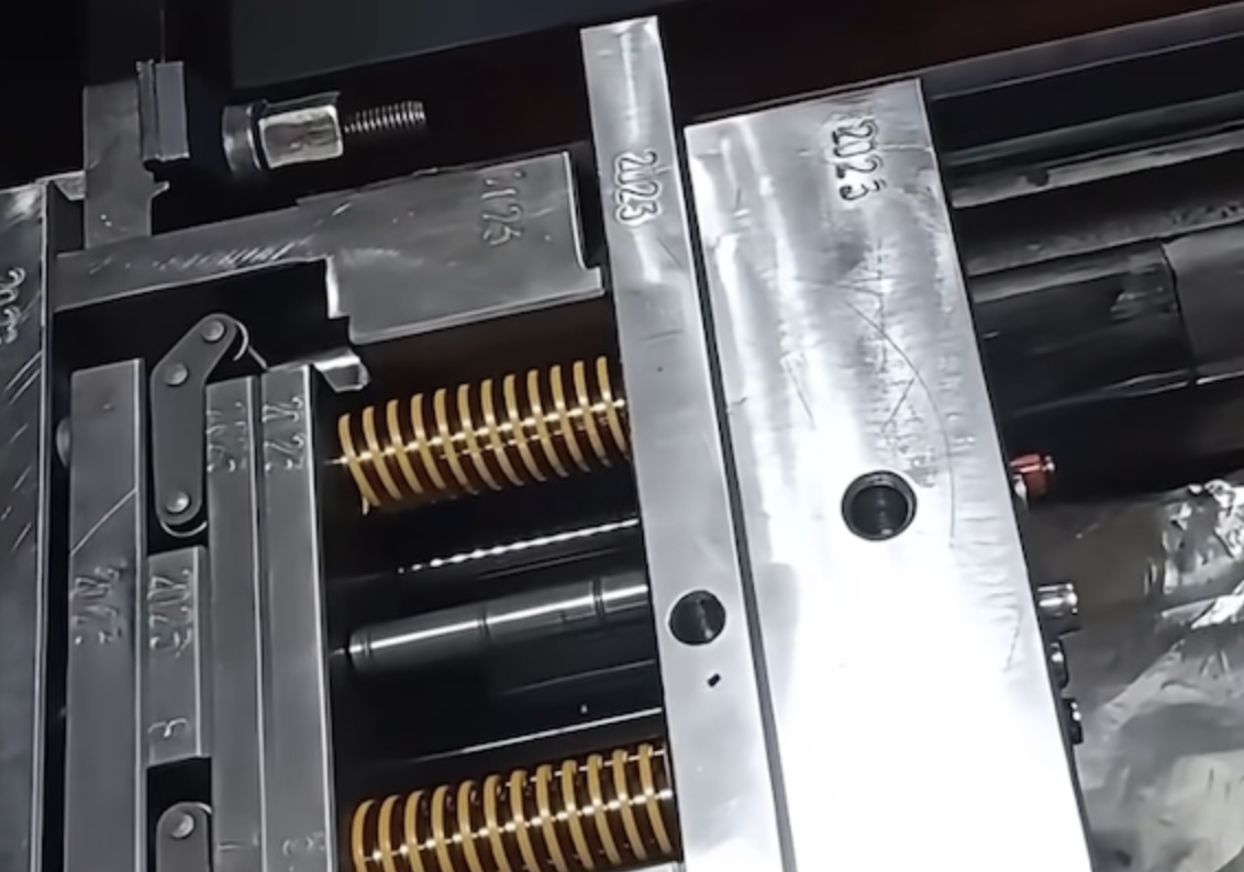
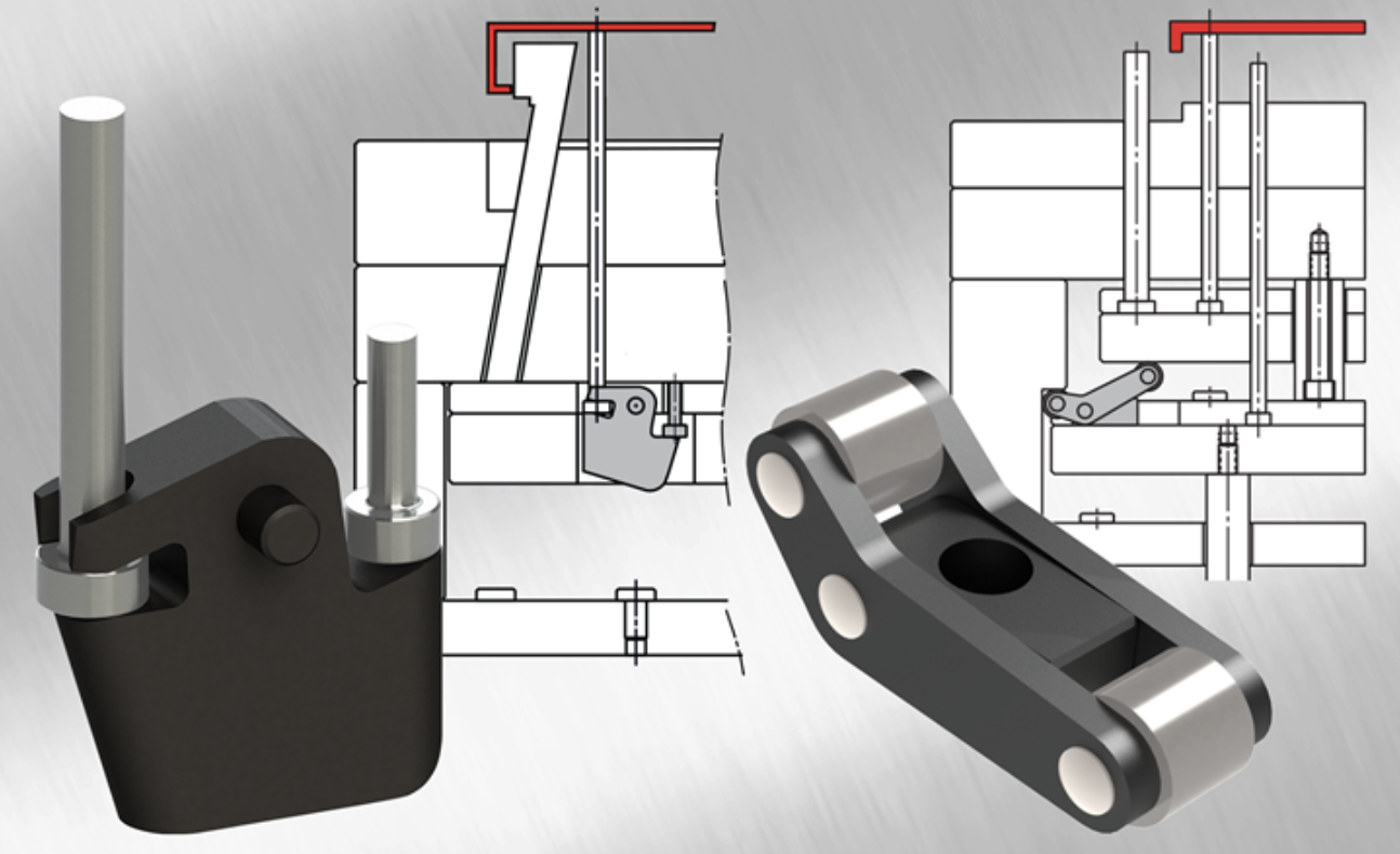
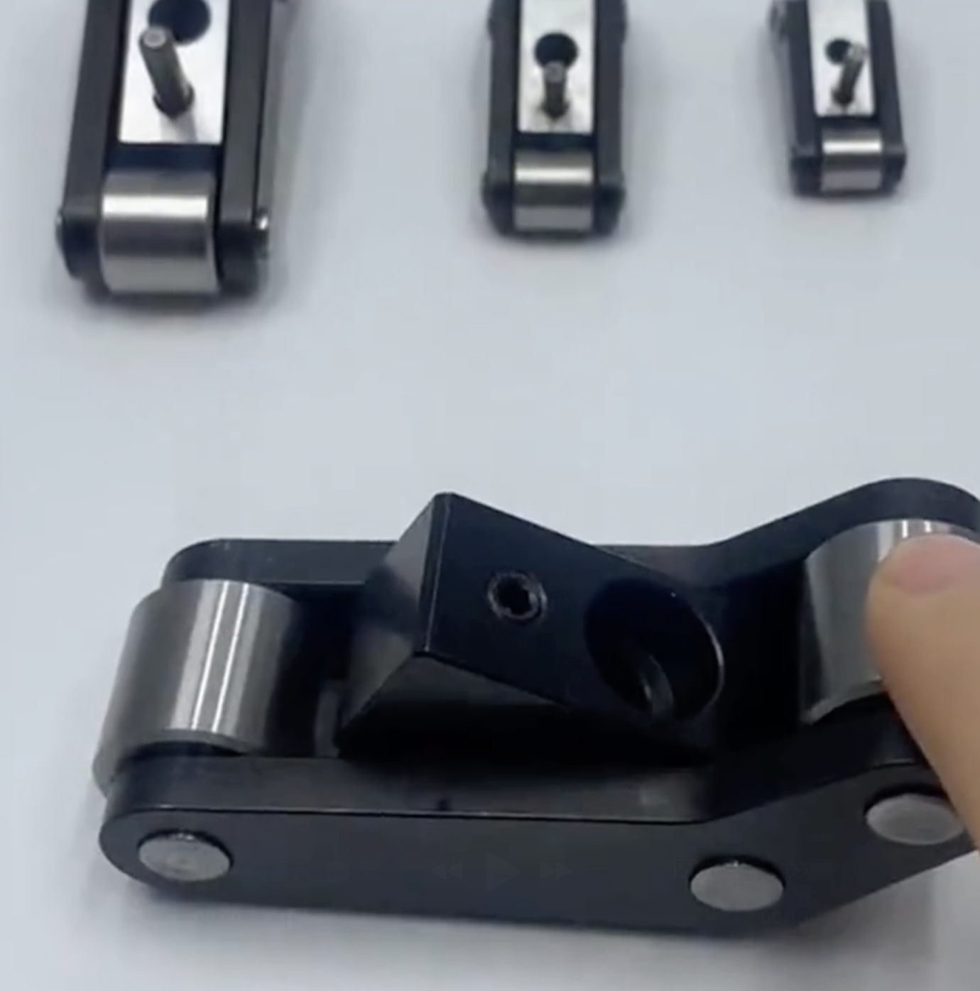
The lever ejection mechanism operates on fundamental mechanical principles. At its heart is a precisely machined rocking lever (the "seesaw") mounted within the ejector housing. Here's the operational sequence:
Phase 1: First-Stage Ejection
As the injection machine's ejector rod advances, a delay mechanism (typically shoulder screws with springs) temporarily holds back the secondary ejection system. The force instead acts on one end of the rocking lever, causing it to pivot. This pivoting motion drives the primary ejectors—usually connected to the problematic features—to move first, breaking the initial bond or vacuum.
Phase 2: The Transition
After a precisely calculated travel distance (typically 3-10mm), the delay mechanism reaches its limit. The lever can no longer pivot on the primary side, effectively locking that portion of the system.
Phase 3: Second-Stage Ejection
With the primary system now stationary, continued force from the machine ejector rod transfers through the locked lever to activate the secondary ejectors. These pins then push the entire part off the core, completing the ejection sequence cleanly and safely.
Direct Comparison: Mechanical Lever vs. Hydraulic Systems
Aspect | Lever Ejection Mechanism | Hydraulic Sequential Ejection |
Initial Cost | Low to moderate. Only requires standard mold components and machining. | High. Requires cylinders, manifolds, valves, and hydraulic connections. |
Operating Cost | Virtually zero. No ongoing fluid, filter, or seal maintenance. | Ongoing. Hydraulic fluid, filters, seals, and potential leakage management. |
Complexity | Medium mechanical complexity. Well-understood by most toolmakers. | High. Requires integration of hydraulic and control systems with mechanical tooling. |
Reliability | Excellent. Fewer failure points, purely mechanical action. | Good, but subject to seal wear, fluid contamination, and valve failures. |
Setup & Adjustment | Fixed travel designed into tool (requires disassembly to modify). | Adjustable via hydraulic controls during operation. |
Mold Thickness | Increases moderately to accommodate lever mechanism. | Can be more compact in the ejector area, but needs space for cylinders. |
Lead Time | Standard machining time only. | Extended for sourcing and integrating hydraulic components. |
Design Considerations for Optimal Performance
When implementing a lever ejection mechanism, our engineering team focuses on several critical factors:
1. Stroke Ratio & Lever Arm Design
The relationship between the lever arms determines the mechanical advantage and travel ratio. We typically maintain a 1:1 to 1:1.5 ratio for balanced force distribution.
2. Delay Mechanism Precision
The shoulder screws and springs must be carefully calculated to provide consistent delay without excessive resistance. We often use pre-load adjustable springs for fine-tuning during tryout.
3. Material Selection & Heat Treatment
The rocking lever experiences significant cyclic loading. We recommend through-hardened tool steels (like S7 or H13) at 48-52 HRC for optimal wear resistance without brittleness.
4. Lubrication Strategy
Permanent grease grooves or installed lubricators prevent galling and ensure smooth operation over the mold's lifetime.
5. Safety & Reset Systems
Robust return springs and early engagement return pins are non-negotiable for ensuring complete reset before mold closure.

When to Choose Lever Ejection Over Hydraulic Systems
Based on our extensive experience, we recommend the lever mechanism when:
✅ Budget is a primary concern – Save 20-35% compared to hydraulic systems
✅ Production runs are long – Mechanical systems excel in high-cycle applications
✅ Maintenance access is limited – No hydraulic leaks or fluid changes needed
✅ Mold space allows – Typically requires 40-60mm additional ejector housing height
✅ Timing is fixed – The sequential timing is determined and won't need adjustment
Conversely, hydraulic systems may be preferable when:
❌ Adjustable timing during operation is essential
❌ Extremely limited space in the ejector area exists
❌ Multiple independent sequential actions are required
❌ The mold already incorporates hydraulics for other functions

Common Misconceptions Debunked
"It's an outdated technology."
Reality: While the principle is decades old, modern CNC machining, superior materials, and precise engineering have elevated the lever ejection mechanism to new levels of reliability and performance. It remains in widespread use across automotive, medical, and consumer electronics tooling.
"It's difficult to repair."
Reality: With proper design, the mechanism is serviceable. Strategic placement of access points allows for component replacement without complete mold disassembly.
"The timing cannot be adjusted."
Reality: While not as easily adjustable as hydraulic systems, modifications can be made during maintenance periods by replacing or modifying the delay components—a process our team has streamlined through standardized components.
The Opro tech Advantage
At Opro tech engineering, we don't just implement lever ejection mechanisms—we optimize them for each application. Our proprietary design database includes over 50 variations of the basic concept, tailored for specific challenges like:
· Micro-molding applications with stroke requirements under 2mm
· Multi-cavity family molds requiring synchronized sequential action
· Stack molds with space constraints
· High-temperature materials (like PEEK or PEI) requiring special clearances
Our engineering team conducts FEA (Finite Element Analysis) on every lever component to ensure longevity, and we maintain an inventory of standardized lever components to reduce lead times.
Looking Forward: The Role of Mechanical Solutions in an Automated World
As Industry 4.0 and smart manufacturing transform our industry, one might assume purely mechanical solutions would become obsolete. Our experience suggests the opposite. The reliability, predictability, and cost-effectiveness of mechanisms like the lever ejection system make them ideal foundations upon which to build intelligent tooling.
By integrating sensors to monitor lever position and ejection force, we're creating "smart" mechanical systems that provide data for predictive maintenance without sacrificing the inherent reliability of the mechanical design.
Why This "Old-School" Solution Still Wins
In an era of increasing technological complexity, the lever ejection mechanism stands as a testament to elegant engineering principles. It proves that advanced solutions don't always require advanced technology—sometimes they require advanced thinking about basic principles.
For molders facing sequential ejection challenges, we encourage considering this mechanical approach before defaulting to hydraulic systems. The cost savings are substantial, the reliability is proven, and the simplicity is beautiful.
Ready to explore if a lever ejection mechanism is right for your next project?
Contact our team at danny@opro-tech.com for a free design consultation and cost comparison specific to your application.
We specializes in high-precision injection molds for the automotive, medical, consumer electronics, and packaging industries. With over 20 years of experience and thousands successful projects, we combine traditional craftsmanship with modern technology to deliver tooling solutions that perform in the real world.
#LeverEjection #SeesawMechanism #TwoStageEjection #MoldDesign #InjectionMolding #Tooling #CostEffectiveTooling #MechanicalEjection #PlasticsEngineering #Manufacturing #DFM #MoldMaking
Factory add: No 39, Zhen an west road, Changan town , Dong guan city, China.